


How to Create a Lithophane with Emboss from Image
Introduction
This topic explains how to create a lithophane using an emboss from an image. This tutorial will also show how to import images and use 2 Rail Sweeps, and will also provide information on lithophanes and tips on their creation.
Example
In this example, a color image is used.You can work along with this example using your own image by adjusting the listed sizes appropriately.
Part 1) Open a New File
-
In the File menu, click New.
- With the Part option selected, click OK.
The new part opens with the Feature Manager Design Tree open.
Ensure the document is set to inches. -
Click the
 BobART tab to access the BobArt Tree.
Part 2) Load the Image, Set Size, and Location
Loading the Image
-
In the BobARTtree, right-click
 Images, and click Load Image.
 -
In the Opendialog, select the folder in which the image is saved.
-
At the bottom of the dialog, next to Files of Type, click the arrow and select All Files (at the bottom of the list).
You can also go through the list to find the specific file type you need. -
Select the image and click Open.
The
The Image-___ item is added to the BobART tree under Images. tree that contains the image (Sketch Picture).
Setting the Size and Location
-
By default the UCS is set to Top(X/Y) which is the desired UCS for this example.
-
For this example our image size is X 4.40, Y 4.42.
Deselect the -
The size we set for our image is updated to X 3.00, Y 3.00.
-
In this case we update the location so the other aspects of our project can be placed at the origin.
This can be adjusted by editing the values in the fields, or by placing your mouse over the image and dragging it into the desired position.

Since we want an exact value, we update the X, Y origins to X 0.250, Y 0.250. 
-
If needed we can add a rotation angle to the image, but keeping the edges parallel with the X and Y axis is the desired result in this case, so this value is left to 0.
-
Click OK.
The dialog closes.
Part 3) Creating a Sketch
Creating a Frame
-
In the Shapes group, of the Create 2D ribbon, click
 Rectangle.
The Rectangle dialog opens and the preview appears.
-
Update the Parameters to:
- Dimensions:
- Length = 3.500
- Width = 3.500
- Base Point:
- X = 1.750
- Y = 1.750
- Z = 0.000
- Dimensions:
-
Click OK.

-
Update the Parameters to:
- Dimensions:
- Length = 3.000
- Width = 3.000
- Dimensions:
- Leave the Base Point values as they are and click OK.

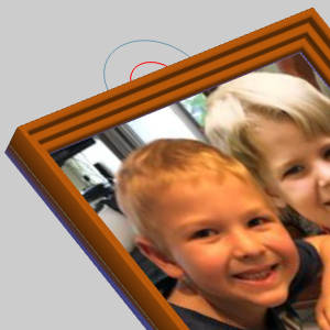
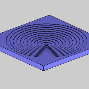
Creating a Loop
-
In the Entity group, of the Create 2D ribbon, click the down arrow under
 Arc, and select
  Arc Center.
The Arc Center dialog opens and the preview appears.
-
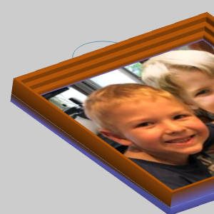
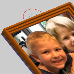
Update the Diameter to 0.500 and hover over the top line to view the possible snap points.
-
Highlight the center snap point and click to place the arc.
-
Click OK to finalize.
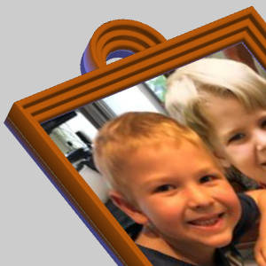
The arc is created and the preview shows the location of the next. -
To create the next arc:
-
Update the Diameter to 1.000.
-
Click OK.
-
Click Cancel to close the function.
-
-
In the Trim Extend group of the Utilities ribbon, click
 Quick Trim.
 -
Click each portion of the arcs which intersects with the frame.


-
Click Cancel to exit the function.
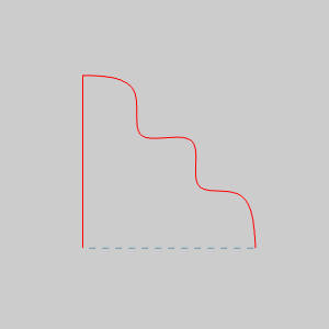
Creating a Cross-Section
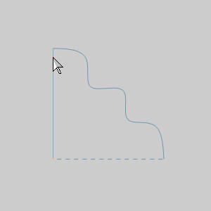
- Create a shape to act as the cross-section of our frame.
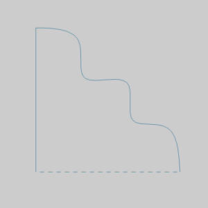
A vertical line and a spline was used in this case, with dimensions keeping it 0.250* 0.250.
Part 4) Define the Canvas
-
In the BobARTtree, right-click
 Emboss Model, and click Edit Canvas.
The Canvas Definition dialog the appears with an outline of the canvas shown at the default size.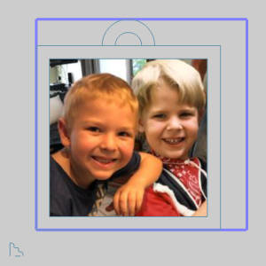
-
By default the UCS is set to
We use the default Origin values to place the lower-left corner of the canvas at the selected origin.
In the Canvas Definition dialog, leave the Originvalues set to X0Y0Z0. -
For this example our Canvas Size does not need to be exact as long as the canvas extends beyond our intended lithophane, which in this case it does.
Canvas Size is left at 4*4. -
In the Parameters group, select the check box for Remove Non-Emboss Area.
This option is the reason our size can be larger than our intended model without needing to be exact.
With this option selected, only the area our features are created in will be a part of the saved stl file. -
In the Parameters group, set the Base Height to 0.126.
This value depends greatly on the method you are using to create the physical lithophane and is explained at the end of the tutorial.Click here to jump to that section. -
In the Material Appearance group, leave the default color.
-
Click OK.
The dialog closes, and the defined canvas appears in the graphics area.
The entire canvas is currently shown because no features have been created.
Part 5) Create the First 2 Rail Sweep Feature
-
In the BobARTtree, right-click
Emboss Model, and click Emboss 2-Rail Sweep.
The Emboss 2 Rail Sweep dialog appears. -
Set a name for the feature.
-
Click the Colordrop downs to view the default options.
-
Select brown.
Define Geometry for Rail 1
-
By default the Selected Geometry list in Rail 1 group has focus.
In the graphics area, select the inner geometry, as shown next.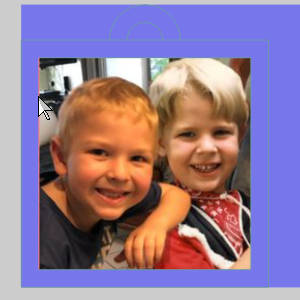
The geometry is added to the list, and the chain is added to the Profile Chain list.
Define Geometry for Rail 2
-
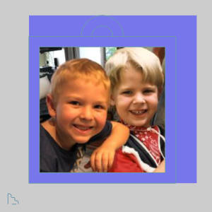
Click in the Selected Geometry list in Rail 2 group to give it focus.
This time, select the outer rectangle.
The result should look like the image shown next
The geometry and chain direction for Rail 2 is now defined.
Tip: By clicking each of the Profile Chains, the direction of the chains will be visible. Currently they should be facing the same direction, which is what we want. To reverse the direction of the chain while in the dialog, click the reverse button. You can accomplish the same thing from the BobArt Tree by right-clicking Rail Geometry, and click Reverse Direction. The selected chain and direction are shown by clicking Rail-Geometryin the BobART tree.
Define the Cross-Section Geometry
-
Click in the Selected Geometry list of the Cross-Section group to give it focus.
-
-
In the Cross-Section group, click in the Profile Chains list box to give it focus, then click Chain(1) to highlight the chain in the graphics area.
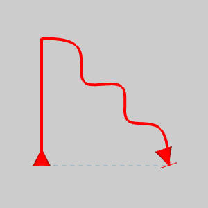
Because we selected the line first, the direction of the chain begins there and points to the final entity.
Important: The direction of the selected cross-section geometry is important because the start point of the cross section is connected to Rail 1 and the end is connected to Rail 2. The cross section is swept along the rails from the starting point to the opposite end. The come of any 2-rail sweep is controlled entirely by the chain direction used for each entity.
Apply and Adjust
-
Click Apply.
-
Rotate the canvas to get a better view of the applied cross-section.

Notice the cross-section gets higher in the corner of the frame.
This is because we are using the Scale Cross-Section Based on Width option.Since the distance from corner to corner is greater, the cross-section is scaled uniformly to the changing distance. -
In the Parameters group, deselect the Scale Cross-Section Based on Width check box and click Apply.
Since the geometry of our Cross-Section was sized accurately, we can utilize its actual height. Had we created a much taller cross-section, this could become an issue here. -
In the Cross-Section group, click in the Profile Chains list box to give it focus, then click Chain(1) to highlight the chain in the graphics area.
In this case we want the highest part of the cross-section to the outside of the frame, so the direction of the cross-section chain needs to be reversed. -
Click the Reverse button next to the Profile Chains list.
-
Click Apply.
The cross-section is updated.
Part 6) Create the Second 2 Rail Sweep Feature
-
In the BobARTtree, right-click
Emboss Model, and click Emboss 2-Rail Sweep.
The Emboss 2 Rail Sweep dialog appears. -
Set a name for the feature.
-
Click the Colordrop downs to view the default options.
-
Select brown.
Define Geometry for Rail 1
-
By default the Selected Geometry list in Rail 1 group has focus.
In the graphics area, select the outer geometry, as shown next to keep the highest part of the cross-section on the outside.
The geometry is added to the list, and the chain is added to the Profile Chain list.
Define Geometry for Rail 2
-
Click in the Selected Geometry list in Rail 2 group to give it focus.
This time, select the inner geometry.
The result should look like the image shown next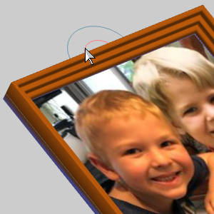
The geometry and chain direction for Rail 2 is now defined.
Define the Cross-Section Geometry
-
Click in the Selected Geometry list of the Cross-Section group to give it focus.
-
-
In the Cross-Section group, click in the Profile Chains list box to give it focus, then click Chain(1) to highlight the chain in the graphics area and verify the correct direction.
Because we selected the line first, the direction of the chain begins there and points to the final entity.
Apply
-
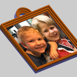
Click OK.
The dialog closes and our frame and loop are complete. -
In the Feature Manager Design Tree, hide the sketch.
Part 7) Create the Emboss from Image
Create the Feature
-
In the BobARTtree, right-click
Emboss Model, and click Emboss from Image.
The Emboss from Image dialog appears. -
Set a name for the feature.
-
Click the Colordrop downs to view the default options.
Select white.
Load the Image
.
-
In the Image section, click Load image.
The Open dialog appears. -
In the Opendialog, select the folder in which the image is saved.
-
At the bottom of the dialog, next to Files of Type, click the arrow and select All Files (at the bottom of the list).
You can also go through the list to find the specific file type you need. -
Select the image and click Open.
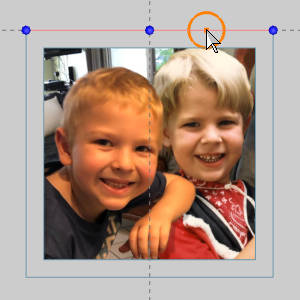
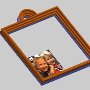
The image is loaded and displayed in the graphics area with the lower-left corner at the origin.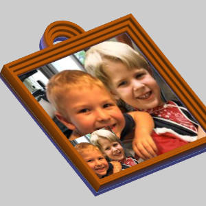
Notice the original image is still visible. -
At the top of the dialog, click
 (Show or Hide all images in the graphics area).
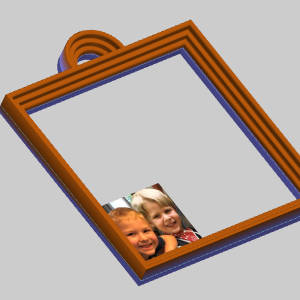
The original image is hidden.
Update the Location and Size
-
In the Origin section, set the X/Y values to 0.250.
-
In the Size section, deselect the Lock aspect ratio check box so we can adjust the these values and their ratio.
-
Set the X Size and Y Size both to 3.000.

Set the Depth and Apply
-
Set the Z Depth to 0.125.
-
Click Apply.
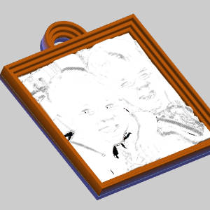
With our application type set to Add, the lightest areas of the image are the highest.
This would actually be the opposite of our intention if we want a lithophane which doesn't appear to be a negative.
Update the Application Type
-
Set the Application Type to Subtract.
-
Click Apply.
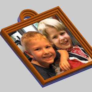
Since we are now using subtract, the image is blocking the result. -
In the Origin section, lower the Z value below -0.125.
-
Click OK to exit the dialog.
Saving the STL File
-
In the BobARTtree, right-click
Emboss Model, and click Save Whole Emboss As Component/STL.
The Export STL File dialog appears. -
Update the Parameters as necessary.
For this tutorial, the defaults are fine. -
Click OK.
The Save As dialog appears. -
Name the file, select the location to save it to and click OK.
This concludes the tutorial.
Tips on Lithophane Creation
The Tutorial Result
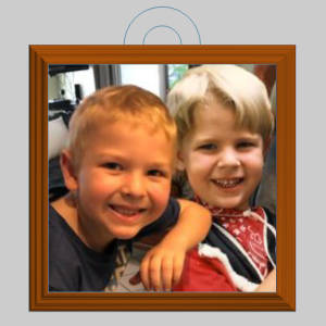
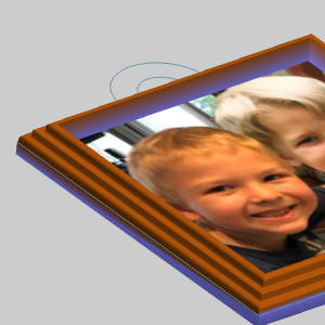
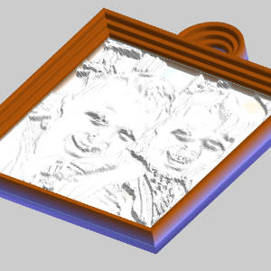
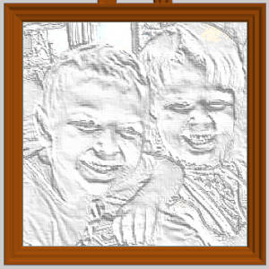
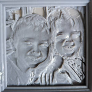
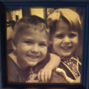
With the result saved it was sent to a slicing software to control how it was printed.From there, it was sent to a 3D printer (Resin) to get the following result:
| Front-facing illumination | Back lit |
|
|
Determining Depths
Lithophane Basics
A lithophane works by back lighting the cut/printed material so the lightest parts of the image allow the most light through, while the darkest parts do not let light through. With this in mind, recall the fifth step of part 4, the base height of the canvas, as well as the Z Depth of the Emboss from Image. How thick should the total result be to allow the proper amount of light through?This depends entirely on the material being used. The more opaque the material, the thinner the lithophane must be.
Testing
The Material
To test how much light can get through the material, first make an educated guess on a depth at which light should not be able to pass through the material. In the example above, an opaque gray resin was used.Being as opaque as it is, 0.120 was thought to be thick enough that the material would prevent light from showing through at that thickness. With the amount of steps used, if this thickness still allows light through, a final thickness which prevents all light from passing through could be inferred by the test.
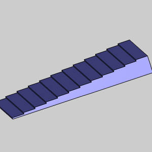
The Test Part
With a thickness in mind a part is created dividing that thickness into many level layers. In the case of the 3D printer, each print begins with 6 base layers overexposed to ensure adhesion to the plate which combine to a total thickness of .0118 inches. I then created a stepped rectangle with each step adding 0.01 inches of thickness. If this was being cut on a machine, a similar approach could be used with a pocketed part.
| 3D Printer Test | Possible CNC Test |
|
|
The Light Source
The light source being used for the final product should also be considered. For instance: halogen light is going to be able to illuminate much thicker material than a single led could. Once printed, the test is placed in front of the light.
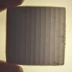
Going from the thickness of my combined base layers, up to the final thickness of the test part, we can see a little light still appears to be able to pass through the final 0.120 inch thickness.
Setting Depths
Since we found 0.120 inches to almost completely block light, we decided the depth of the feature should be 0.125. The Emboss from Image feature is subtracted from the canvas, so our canvas must be slightly thicker. For this reason, we set the Base Height of our canvas to 0.126.
This conclude the Determining Depths section.
If you jumped to this section from the link in the above steps, click here to jump back to that step.