


Emboss from Image Example 1
Introduction
This help topic explains how to create an Emboss from Image feature.The entire process is explained step-by-step.Some special tips are provided after the main portion of the tutorial which will show you how to remove an unwanted area of the Emboss from Image feature to create a component.
This tutorial combines four examples.You learn how to create an Emboss from Image, how to Vectorize geometry (Black and White Strategy), how to use Smoothing, and how to Save As a Component/STL.You can use the links at the top right of this page to navigate to each section if you are not completing the entire tutorial.
Example File
If you are connected to the Internet, the part file for this example can be downloaded automatically by clicking the following link: Emboss fromImage Example 1.bbcd
Once you download and saved the zip file, extract the files on your system in an easy place to remember.You can then open the file to use with this tutorial.All files for the tutorials in this help system available for download can be found by clicking on the following link: http://www.bobcad.com/helpfiles.
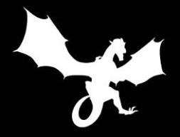
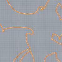
The images in the zip file needed for the Emboss from Image example, Dragon Black and White.png and Dragon BAS.png, are shown next.

Example 1: Emboss from an Image
Part 1) Define Canvas
For this example, you can open the Emboss from Image Example 1.
-
In the BobARTtree, right-click
 Emboss Model, and click Create/Modify Canvas.
 -
In the Opendialog, navigate to the folder in which you saved the example files.
Tip: When locating an image file, it can be helpful to show all file types in the Opendialog.This allows you to see all image files that are contained in each folder.To show all files: at the bottom of the Opendialog, click the Files of Typearrow, and at the bottom of the list, select All Files.
Select Dragon BAS.png and click Open.
The Canvas Definition dialog is displayed.
In this example the canvas is created with the same size as the image.
Tip: Notice that we added the emboss feature before creating canvas.For the Emboss from Image feature, this is a special tip that allows you to easily set the canvas size to the same size as the image.Notice the Canvas Size X and Y values are automatically set based on the image size.You can increase the Canvas Size values if you want to make the canvas larger than the image file.(The canvas size can also be modified after creating the feature.)
Note: The origin of the canvas is the lower-left corner.You can type the coordinate values of a point in the OriginXYZ boxes to define where the canvas origin is located in the graphics area.This example uses the default values of X0Y0Z0 to place the canvas origin at the WCS or world coordinate system.The default model color is used because the canvas and the image are the same size.In this situation, the color of the feature will cover (mask) the canvas color.
-
To close the dialog and create the canvas, click OK.
The Create Emboss from Image dialog is displayed.
Part 2) Add the Feature
-
In the BobARTtree, right-click
Emboss Model, and click Emboss from Image.
Part 3) Define the Feature Parameters
-
For this example, the Originvalues remain at X0Y0Z0.
As with the canvas, the image origin is the lower-left corner of the image.
The Origin values define the position of the image in relation to the coordinate system you created the model on. -
In the Canvas Size group, notice that the X Size and Y Size values are automatically set based on the image size.
The Z Depth uses a default value of 0.100.
This defines the maximum height of the feature and it is not guaranteed to be exactly the specified value.(The information in the image defines the final result. -
Click in the Namebox, and type My at the beginning of the description.
When the feature is added to the BobART tree, it is labeled My Image Emboss 1. -
To select a color for the feature, clickColor.
In the Color dialog, click the desired color, or define a custom color, and click OK. -
The Application Type, Add, is used for this example.
This means that the emboss is added to the model or raised in the positiveZ-axis direction. -
To create the feature using the defined values, click OK.
-
Right-click
 Emboss Model, and click Regenerate.
The result is shown next.


In the previous image, the maximum height in Z is less than 0.100.
The default value of 0.100 is small for this example.
The next step is to modify the Z Depth.
Part 4) Edit the Feature and Regenerate the Model
-
In the BobARTtree, right-click
 My Image Emboss 1, and clickEdit.
 -
In the Canvas Size group, set the Z Depthto 1.00.
-
To accept the change, click OK.
Notice the feature in the BobART tree.The Emboss Model icon and the  My Image Emboss 1 icon are displayed with a red x. This shows that changes have been made that have not been added to the model.Themodel needs to be regenerated.
 -
To add the changes to the model, right-click
Emboss Model,and click Regenerate.
Note: Every time that you modify the parameters or the geometry/image of an emboss feature, the results are not added to the model until you Regenerate to calculate the changes.
The maximum Z Depth of the feature is now 1.00.
Notice that the emboss is much more prominent than in the previous result.


The Emboss from Image example is complete.
In the next part of this tutorial, you learn how to Vectorize an image that is used to create the profile of the dragon.The geometry is then used to contain a Smoothing feature.This geometry is also used to create an emboss feature that contains all of the areas around the dragon.Aftercreating the second feature, the dragon can then be saved as a component that only contains the dragon, not the entire emboss from image feature.
Example 2: Vectorize - 2 Color (Black and White) Strategy
Part 1) Vectorize an Image - 2 Color (Black and White) Strategy
For this part of the tutorial, a black and white image of the dragon is loaded into the system and vectorized to create geometry that is used later.
-
To hide the current embossed model, right-click
Emboss Model,and click Blank/Unblank. -
In the
 BobARTtree, right-click
  Images, and click Load Image.
-
In the Opendialog, locate and select Dragon Black and White.png, and click Open.
Tip: When locating an image file, it can be helpful to show all file types in the Opendialog.This allows you to see all image files that are contained in each folder.To show all files: at the bottom of the Opendialog, click the Files of Typearrow, and at the bottom of the list, select All Files.
The image is loaded into the graphics area with the image origin (the lower-left corner) placed at the WCS or world coordinate system origin.Note that an Image feature is added to the BobART tree under Images.(If you want to change the default location, right-click![]() Image-image name,and click Edit.)
Image-image name,and click Edit.)
Note: When viewing images in the graphics area, the Top view must be used (press Ctrl+1). When you rotate to any other viewing position, the image is no longer visible.

-
Under
Images, right-click  Image-Dragon Black and White, and click Vectorize.
The Raster to Vector dialog is displayed. -
In the Vectorize Strategygroup, select 2-Level (Black/White) Strategy.
The Threshold Value is set to 2.(For this example, no changes are made to the default settings.) -
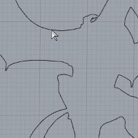
To vectorize the image using the defined parameters, click OK.
-
To hide the image and view the geometry, right-click
Image-Dragon Black and White, and click Blank/Unblank.
[You can also use the keyboard shortcut I(the letter I, for Image). Click anywhere in the graphics area (so that it has key focus) and press I to toggle the visibility of the image.This method can be used instead of using the Blank/Unblank method, meaning that they do not work together.You use one or the other.]

This concludes the vectorization example.The geometry that you created is used in the next three parts.
Example 3: Using Smoothing
Part 1) How to Use Smoothing
When you zoom-in to view the model up close, you can see that the result of embossing the height-map image has left a texture/grainy appearance on the model.This appearance may or may not be desired.For this example, we use smoothing to remove this from the model surface.The areas of the model that we want to improve are shown next.

-
Right-click
Emboss Model, and click Smoothing. -
In the Boundary Based Smoothing dialog, leave the default settings, and click OK.
-
In the BobARTtree, under
 Smoothing 2, right-click
 Geometry,and click Re/Select.
Zoom in, if needed,


Repeat this process for the following chain.


To confirm the selection, click OK.
Note: When using a Smoothing feature, by default, the smoothing is applied to the entire model.(You do not have to select geometry.) When you select geometry to contain the smoothing feature, it is only applied within the selected boundaries.

To show the embossed model again, right-click ![]() Emboss Model, and click Blank/Unblank.
Emboss Model, and click Blank/Unblank.
-
To update the model, right-click
Emboss Model, and click Regenerate.
The result is shown next.
You can see that the surface of the model has been improved, but it can still be improved further. -
In the BobARTtree, right-click
Smoothing, and click Edit.
In the Smoothing Parametersgroup, change the Smoothing Window Size to 0.100.
This increases the amount of smoothing applied. -
Click OK and Regeneratethe model, as done previously.
The result is shown next.

The surface of the model has been greatly improved and the smoothing is now complete.This concludes the Smoothing portion of this tutorial.
Part 2) Create an Offset
In the next part of this tutorial, you create an Emboss Regular feature.The geometry that was created from the boundary of the image is the same size as the model/feature.Because they are the exact same size, you offset the geometry to assure that no artifacts are created at the edge of the model.
-
 Offset.
 -
-
- In the document toolbar, click
 to enable selection mode.
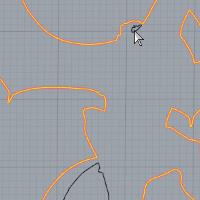
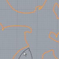
Zoom in to view the outer profile.
Press and hold Shift,and click anywhere on the inner rectangle.
Make sure to select the smaller rectangle and not the offset that you just created.

-


Now the boundary that is used to create the Emboss Regular feature is larger than the model.
This assures that the Emboss Regular feature covers all unwanted areas of the model.
Part 3) Create a Regular Emboss
For this part of the tutorial, a regular emboss feature is created that contains all of the unwanted areas of the Emboss from Image feature.Thisallows us to save only the area of the dragon as a component/stl.
-
In the BobART Manager, right-click
Emboss Model, and click Emboss Regular. -
In the Embossdialog, click Color.
Select a new color for the feature, and click OK.
In the Emboss dialog, click OK.(The parameters for this feature are not important, so the default values are used.) -
Under
 Regular Emboss 3 - Add, right-clickGeometry,and click Re/Select.
 -
-
To confirm the selection, click OK.
-
To add the changes to the model, right-click
Emboss Model, and click Regenerate. -

The model now contains two emboss features, the original Emboss from Image and the Regular Emboss that was added to surround the dragon emboss.When you save an individual emboss as a component, only the area defined by the selected feature issaved.Because the Regular Emboss covers all of the area around the dragon, it is not included when saving the Emboss from Image as a component/.stlfile.
Part 4) Changing the Model Resolution
When the canvas is created for emboss features, the Resolution is automatically set based on the size of the canvas.You can increase the Resolution some to help improve the model appearance.You may otherwise want to lower the resolution to achieve a different appearance or to conserve system resources during the creation process.
Tip: The Resolution parameter that is found in the Canvas Definition dialog is the DPI, or dots per inch, of the model.When increasing the resolution, you must remain within reasonable limits to avoid running out of system resources.Larger resolutions require more processing power and may not be beneficial in the end result when machining the model.The level of detail in the model only needs to match the level of detail with which it is machined.
-
In the
BobARTtree, right-click Emboss Model, and click Create/Modify Canvas. -
In the Canvas Parameters dialog, notice the value in the Resolutionbox.
For this example, the resolution is currently
Just to see how the resolution is updated, in the Canvas Size group, change the Xvalue to 20.00, and pressTab.
The resolution is updated based on the canvas size.
(Change the X value back to18.2361.) -
In the Resolutionbox, type 125.
-
To close the dialog, click OK.
-
To update the model, right-click
Emboss Model, and click Regenerate.
(Calculation times increase when the resolution is increased.)
The increased resolution for this example actually starts to cause a grainy appearance to return, which was removed earlier by the Smoothing feature.(Increasing the Resolution creates a more detailed model.In this case, the increase does not improve the appearance of the model.)
Before saving the component in the next part, change the Resolution back to
Example 4: Creating a Component (Individual Feature)
Part 1) Create a Component (Save As Component/STL)
The BobART module now includes the ability to save individual emboss features (or the entire model) as a component.Saving as a component means that the feature (or model) is saved as an .stl file.The component can then be used to create an Emboss from Component feature.The following steps are used to create a component from a single feature.
-
In the
BobARTtree, right-click the top level item of the feature.
For this example, right-click My Image Emboss 1, and clickSave as Component/STL. -
In the STL Save Option dialog, click OK.The default tolerance value is used.
Tip: You can decrease the tolerance (make the value smaller) to create a more accurate model if necessary.However, decreasing the tolerance increases the size of the saved file, and it may not actually be necessary (meaning that it doesn't improve the machining of the part). The default tolerance is a good starting point.You can increase the tolerance (for example, to
-
In the Save Asdialog, select the folder in which you would like to save the component.
-
In the File Namebox, type the name of the component.
For this example, type MyDragon Component. -
To save the file, click Save.
The result of the component is shown next.(The component was opened in a new file to show the result.)


The component is finished.This concludes the How to Create a Component portion of this tutorial.
The component is used in the How to Create an Emboss from Componenttutorial.
To learn how to save the entire model as a component, view How to Save Whole Emboss As Component/STL.
Important Information
This section explains why the process used in this example was necessary to create the dragon component from the Emboss from Image feature (using only a specific area of the feature).
It is important to understand why the process used in this tutorial was applied to remove the areas around the dragon.The BobART module now includes the ability to remove the non-embossed areas of an embossed model.This option, Remove Non-Emboss Area, is found in the Canvas Definitiondialog.This option can remove excess canvas (that is larger than the Emboss from Image feature), however, it does not have an effect on the Emboss from Image feature itself, because the entire area of the image is a part of the emboss.
Another feature in BobART is the ability to create components using the entire model (Save Whole Emboss As Component/STL) or individual emboss features (Save as Component/STL). The Save as Component/STL option saves only the area defined by the selected feature.Any additional emboss contained within the same area is not included in the component.This is the reason that the Regular Emboss was added to the embossed model.The Regular Emboss feature covered all of the undesired areas around the dragon.When the Emboss from Image feature is saved as a component/.stl file, none of the areas contained in the regular emboss are included in the component.
Related Topics
How to Create an Emboss from Component