


Deburr 3 Axis Example 2
Introduction
This tutorial explains how to create a Deburr operation and adjust that operation to output in 3 Axis.
Example File
If you are connected to the Internet, the part file for this example can be downloaded automatically by clicking the following link: Deburr 3AxisExample 2.bbcd
Once you download and saved the zip file, extract the files on your system in an easy place to remember.You can then open the file to use with this tutorial.All files for the tutorials in this help system available for download can be found by clicking on the following link: http://www.bobcad.com/helpfiles.
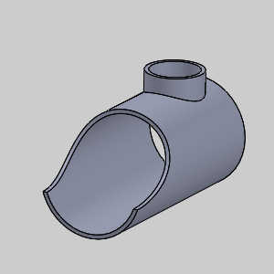
In the example file provided, the Tool Crib is already equipped with the necessary tools and the stock and Machine Setup are already defined.The part is simulated using the BC_3x_Mill machine.
Part 1) Add the Feature
-
 CAM Tree tab
-
Right-click
 Machine Setup and click Mill Multiaxis.
 -
In the Multiaxis Wizard, click Deburring.
-
Click Next>>to go to the Posting dialog box.
Part 2) Define the Posting Parameters
-
The Work Offset # is automatically set to the value defined in the Machine Setup dialog box.
You can change the value here to update the Work Offset # for the feature. -
Click Next>>to go to the Multiaxis Postingdialog box.
Part 3) Define the Multiaxis Posting Parameters
-
Notice, at the top of the dialog box, that the Use Machine Settings checkbox is selected.
This means that the Multiaxis Posting parameters for the feature use the same parameters as the machine that is selected in Current Settings.
You can clear the Use Machine Settingscheck box to define the Multiaxis Posting parameters of the feature separately from the current machine settings.
For this example, no changes are needed (more information is provided later). -
Click Next>>to go to the Tool page.
Part 4) Define the Tool Parameters
-
In the Tool page, click Tool Crib.
The Tool Crib dialog appears. -
Click ENDMILL FINISH and select the finishing tool.
At the bottom of the dialog box, click OK. -
Click Next>>to go to the Parameters.
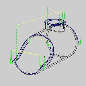
Part 5) Surface paths
-
In the Geometry input group, click the ellipses button next to Part surfaces.
The Mill Multiaxis wizard disappears and the -
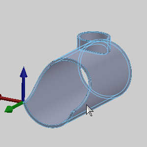
Select the check box for Select whole bodies.
-
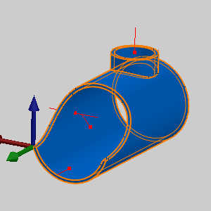
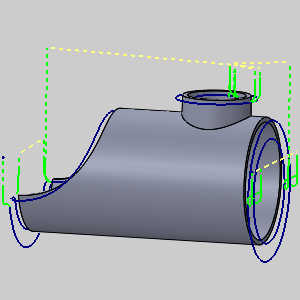
Select the model.
-
Click OK.
The Mill Multiaxis Wizard returns. -
In the Surface Quality group, set the Cut tolerance to 0.001.
This will reduce the calculation time and can be adjusted after we obtain the desired result.
Part 6) Tool axis control
-
At the top of the wizard, click the Tool axis control tab.
-
In the Tilting group, set the Machining type to 3 axis.
-
Click Compute.
Part 7) Edit the tool
-
In the CAM Tree, right-click the feature and select Edit.
-
In the tree on the left of the wizard, click Finish.
-
In the Tool page, click Tool Crib.
The Tool Crib dialog appears. -
Click LOLLIPOP and select the tool.
At the bottom of the dialog box, click OK. -
Click Compute.

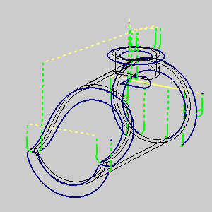
Notice the additional places toolpath has automatically been placed now that we are using a tool capable of undercuts.
Part 8) Simulation
For more help using simulation, view Getting Started with Simulation.
-
To view the program, in the Quick access menu of the CAM Tree, click
 Simulation.
 -
Click Play to view the current operation.
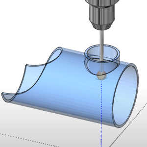
Notice the operation able to do undercuts.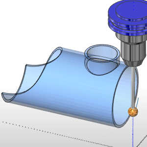
Notice the bottom edge on this side of the part is not finished in order to avoid a collision between the top extrusion and the tool arbor. -
To close simulation, in the
 Exit Simulation.
Part 9) Edit the feature
-
In the CAM Tree, right-click the feature and select Edit.
-
In the tree on the left of the wizard, click Lollipop.
-
In the Tool page, update the Protrusion Length to 4.000.
For this example we will leave the tool in by sheer willpower. -
Click Compute.
This concludes the example.