


Deburr 5 Axis Example
Introduction
This tutorial explains how to create a Deburr operation and adjust that operation to output in 5 Axis.
Example File
If you are connected to the Internet, the part file for this example can be downloaded automatically by clicking the following link: Deburr 5AxisExample.bbcd
Once you download and saved the zip file, extract the files on your system in an easy place to remember.You can then open the file to use with this tutorial.All files for the tutorials in this help system available for download can be found by clicking on the following link: http://www.bobcad.com/helpfiles.
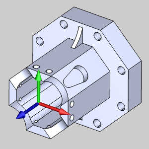
In the example file provided, the Tool Crib is already equipped with the necessary tools and the stock and Machine Setup are already defined.The part is simulated using the BC_Hermie_C20U machine.
Part 1) Add the Feature
-
 CAM Tree tab
-
Right-click
 Machine Setup and click Mill Multiaxis.
 -
In the Multiaxis Wizard, click Deburring.
-
Click Next>>to go to the Posting dialog box.
Part 2) Define the Posting Parameters
-
The Work Offset # is automatically set to the value defined in the Machine Setup dialog box.
You can change the value here to update the Work Offset # for the feature. -
Click Next>>to go to the Multiaxis Postingdialog box.
Part 3) Define the Multiaxis Posting Parameters
-
Notice, at the top of the dialog box, that the Use Machine Settings checkbox is selected.
This means that the Multiaxis Posting parameters for the feature use the same parameters as the machine that is selected in Current Settings.
You can clear the Use Machine Settingscheck box to define the Multiaxis Posting parameters of the feature separately from the current machine settings.
For this example, no changes are needed (more information is provided later). -
Click Next>>to go to the Tool page.
Part 4) Define the Tool Parameters
-
In the Tool page, click Tool Crib.
The Tool Crib dialog appears. -
Click ENDMILL FINISH and select the finishing tool.
At the bottom of the dialog box, click OK. -
Click Next>>to go to the Parameters.
Part 5) Surface paths
-
In the Geometry input group, click the ellipses button next to Part surfaces.
The Mill Multiaxis wizard disappears and the -
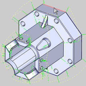
Select the check box for Select whole bodies.
-
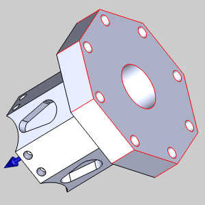
Select the model.
-
Click OK.
The Mill Multiaxis Wizard returns. -
In the Geometry input group, click the ellipses button next to Exclude Edges.
The Mill Multiaxis Wizard disappears and the -
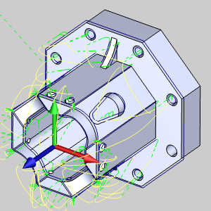
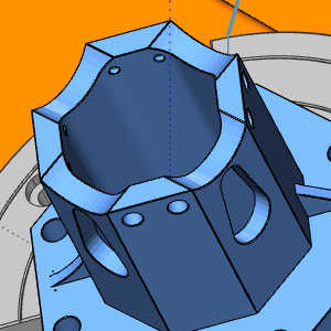
Hover over the back edge as seen in the image below.
With the edge highlighted, right-click and select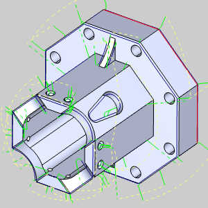
-
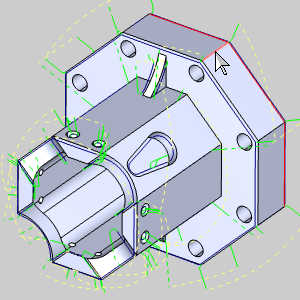
Select the edge along the outer diameter of the part as seen in the image below.
-
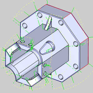
Repeat this for the remaining edges.
-
Rotate the part and select the edges on the back.
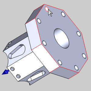
With these edge selected, we will avoid the cutting the jaws holding the part in place. -
Click OK.
The Mill Multiaxis Wizard returns. -
In the Surface Quality group, set the Cut tolerance to 0.001.
This will reduce the calculation time and can be adjusted after we obtain the desired result.
Part 6) Link page
-
Click the Link tab to move to that page.
-
In the Clearance area group, set the Type to Automatic.
-
In the Links group, set the Type to Clearance blend spline.
-
Click Compute.
Part 7) Simulation
-
To view the program, in the Quick access menu of the CAM Tree, click
 Simulation.
 -
Click in the File tab and select Options to launch the Machine Simulator Options dialog.
-
Make sure the check box for Collision & Gouge is selected in the Popup Notifications group.
-
Click OK.
-
Click Play to view the current operation.
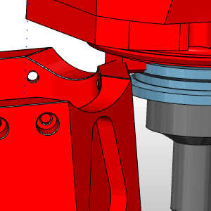
Notice the crash.
We will need to adjust the allowable angle of tool to correct this. -
To close simulation, in the
 Exit Simulation.
Part 9) Edit the feature
-
In the CAM Tree, right-click the feature and select Edit.
-
In the tree on the left of the wizard, click Parameters.
The Surface paths page appears and the other tabs become available. -
Click the Tool axis control tab.
-
In the Tilting group, select the Tilt range check box.
-
Set the Min.value to 25.
-
Click Compute.
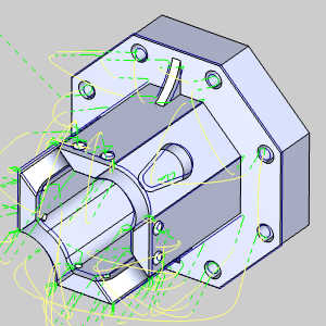
Notice the slight tilt of the toolpath now.
Part 10) Simulation
For more help using simulation, view Getting Started with Simulation.
-
To view the program, in the Quick access menu of the CAM Tree, click
Simulation. -
Click Play to view the current operation.
Notice the part is now cut without collision. -
To close simulation, in the
Exit Simulation.
This concludes the example.