


Creating Revolved Stock
Introduction
In this example you learn how to create stock by revolving wireframe geometry. This example will also provide links to related topics.
Creating the Stock
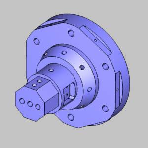
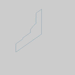
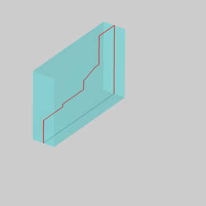
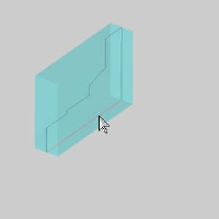
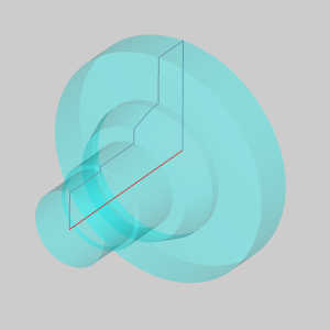
The following images show our example part and the profile that we created to revolve for our stock geometry. For this lesson, imagine we have already turned the part on our lathe and now we want to do some milling, so we need create stock that represents our current part.
Part 1) Select the Stock type
By default rectangular stock is selected.
- In order to create revolved stock, under Stock
Type, select
 Revolve.
The Selected Geometry list appears, and automatically has focus, allowing you to select geometry to revolve into stock.
Part 2) Select Geometry
With the Stock Type selected we are ready to select the geometry.
-
Select all geometry to be revolved.
The geometry is added to the Selected Geometry list.
Part 3) Set the Revolve Axis
Note: By default, the Revolve Axis section of the Stock Definition page is set to Along X Axis. If this is the axis to be utilized, simply press Calculate Stock. Otherwise, select another axis option from the drop down list and Calculate Stock, or follow the remaining steps.
-
Under Revolve Axis, select the Pick Axis option.
The Rotation Axis list box is automatically given focus to allow you to select geometry to add to it. -
Select the individual line representing the Rotation Axis.
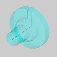
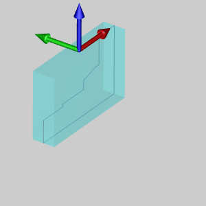
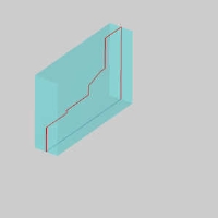
The Stock is automatically revolved.
- When you are finished defining the stock geometry, click
 next to go to the Machine
Setup.
next to go to the Machine
Setup.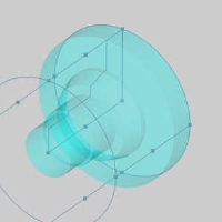
Bounding geometry is automatically created to


Mill Turn Revolved Stock Tips
The process of creating revolved stock for Mill Turn jobs is the same as for Mill jobs. The following section describes a few key points of using the revolve stock type for Mill Turn jobs.
Drawing Plane
The geometry that you create for revolved stock does
not have to be drawn in the XZ plane, but if you are going to use
the same geometry to create turning features, then draw it in the XZ plane
of the machining origin (Machine Setup coordinate system) so you do not
need to modify the geometry later. (Wireframe geometry for turning features
must be drawn in the XZ plane of the machining origin.)