


How to Create a Toolpath Pattern - Translate
Introduction
This tutorial explains how to create a toolpath pattern using the Translate option. The example provided shows how to create a toolpath pattern for two features separately. The first feature is patterned using coordinate values (Delta method), and the second feature is patterned by selecting geometry (Sketch/Enter method). Both methods define the distance that the pattern is translated.
Example Part
If you are connected to the Internet, the part file for this example can be downloaded automatically by clicking the following link: Toolpath PatternTranslate Example 1.bbcd
Once you download and saved the zip file, extract the files on your system in an easy place to remember.You can then open the file to use with this tutorial.All files for the tutorials in this help system available for download can be found by clicking on the following link: http://www.bobcad.com/helpfiles.
In the example file provided, the stock and Machine Setup are already defined for the part.
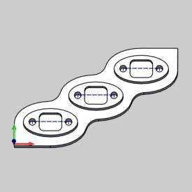
In the example file provided, the first two features, a pocket and two drill holes, are already created for the part. The toolpath patterns are added to copy the defined features to the non-machined areas of the part. In this example, you add toolpath patterns to each feature individually. This is done instead of patterning all of the features in the Machine Setup, because you may want to add other machining features that do not need to be included in the patterns.
![]()
Part 1) Pattern the First Feature
In the following steps, the distance between features is already known, so Delta values are used to define the distance that each feature is copied from the current position. For example, you can use any point of one pocket and measure the distance in X and Y to the same point of the next pocket.
-
In the CAM Tree Manager, below
 Machine Setup, right-click
  Feature 2 Axis, and click Add Toolpath Pattern.
 -
In the Toolpath Pattern dialog, click Translate, and click Next>>.
-
With Deltaselected, in the Copies field, type 2.
This creates two copies of the current feature.
![]()
-
Under Delta, in the X box, type 2.500.
This defines the distance between each feature along the X-axis of the machining coordinate system.
![]()
-
In the Y box, type 1.500
This defines the distance between features along the Y-axis of the machining coordinate system.
![]()
-
To compute the toolpath pattern, click OK.
![]()
You can see that the original feature is copied twice and patterned by the specified values.
Part 2) Pattern the Hole Feature
In the following steps, instead of entering values for the distance between features, geometry is selected directly from the part model. This method is helpful when you have a part but do not know the distances to use. The start and end points that are selected create a line that is used to define the distance that each pattern copy is moved.
Note: Using either method all features can be done at once by applying the toolpath pattern to the machine setup itself, or dragging and dropping the exiting pattern from the single feature to the machine setup.
- In the CAM Tree, right-click
 Feature Mill Hole, and click Add Toolpath Pattern.
 - In the Toolpath Pattern dialog, click Translate,and click Next>>.
- In the Translategroup, click Sketch/Enter.
- In the Copiesfield, type 2.
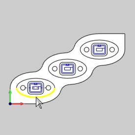
- To select geometry that defines the start point, under Start, clickPick.
The dialog disappears and the Toolpath Pattern Picking dialog appears in the Data Entry Manager. - Pick the snap point seen below by hovering over the surface edge and selecting the snap point when it appears.
- The item is added to the list. Click OK.
The Toolpath Pattern Picking dialog reappears.
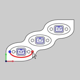
Notice that the Start values are automatically updated. The Start values are X
Important: the values here are not too important as long as the end point picked is the proper distance away from the start. A different selection could be used from what is shown in the image so long its match in the next iteration of the pattern is selected for the end value.
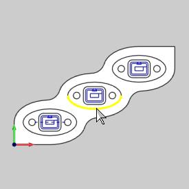
- In the End group, to select geometry, clickPick.
The dialog disappears and the Toolpath Pattern Picking dialog appears in the Data Entry Manager. - Select the matching point of the next iteration as seen below.
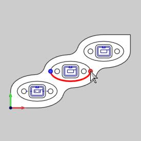
The position is added to the Selected Geometry list. - The item is added to the list.Click OK.
The Toolpath Pattern Picking dialog reappears.
Notice that the Start values are automatically updated. The Start values are: X - To calculate the toolpath pattern, click OK.
Tip: To hide a toolpath pattern, in the CAM Tree, right-click ![]() Toolpath Pattern and click Blank/Unblank Toolpath Pattern. Alternatively, if you hide the original feature, the original feature and the pattern are hidden.
Toolpath Pattern and click Blank/Unblank Toolpath Pattern. Alternatively, if you hide the original feature, the original feature and the pattern are hidden.
Part 3) Simulate the Program
-
In the quick access toolbar, of the CAM Tree Manager, click
 .
.
(Alternatively, you can right-click ![]() Milling Job,and click Simulation.)
Milling Job,and click Simulation.)
After simulating, the stock model appears as shown next.
![]()
-
To close the simulation, click
 Exit Simulation.
This concludes the tutorial.