


The Lathe Wizard Geometry Selection
Introduction
This topic explains geometry selection for a Turning feature. This topic will explain the option, provide images of example geometry, and provide a link to the next topic.
Geometry Selection
The Geometry Selection dialog of the Lathe Wizard displays as seen below. This is the first page that you see when you add a feature. The first step is to assign geometry for the feature. This topic will go over how to select geometry for this feature.
Geometry Selection
|
|
|
Geometry Selection
- Select Geometry - opens the

|
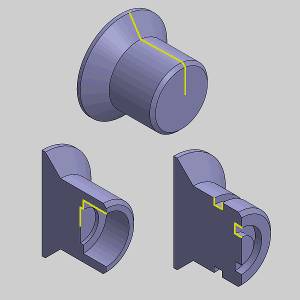
Surface Selection |
Line Selection |
Result |
|
|
|
|
Re/Select Geometry dialog
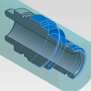
When creating any Turning feature, BobCAM analyzes the profile of the selected geometry. The XZ plane is considered the zero degree starting point. BobCAM analyzes the part in different section planes. The First section plane start angle and the Interval angle between section planes options decide exactly how many section planes are used to analyze the part. For example, if First section plane start angle is set to zero degrees (the XZ plane) and Interval angle between section planes is set to 90 degrees, the profile of the part is analyzed in four different section planes.
Tip: The location of the section planes for a part can be viewed by selecting the Display Section Planes check box in the Selection Manager.
-
 OK - Accepts the updates to the parameters and closes the dialog.
 -
 Cancel - Discards the updates to the parameters and closes the dialog.
Note: When the dialog is first launched through the wizard, these options will both return you to the wizard.
Feature Extraction Method
-
 Section Planes
 -
 Spun Profile
Section Planes
This section appears when the Section Planes method is selected for the Feature Extraction Method.
-
 Display
Section Planes - Select the check box to show the section planes location on the
part as a preview in the graphics area.
Display
Section Planes - Select the check box to show the section planes location on the
part as a preview in the graphics area.  Display
Section Planes - Clear the check box to hide the section planes preview in the graphics area.
Display
Section Planes - Clear the check box to hide the section planes preview in the graphics area.
-
Enter Section Angles - The following parameters display when Enter
Section Planes is selected.
-
Start Angle - is the reference angle to which BobCAM begins analyzing the profile of the feature geometry. The zero degree location is the XZ plane (by default).
-
Interval Angle - a new section plane is created at this interval for determining the number of section planes used to analyze the part geometry.
-
The Section Angles box displays all angles at which a section plane is created. You can click the angles listed in this box to highlight the section plane in the graphics area (Display Section Planes must selected.)
-
-
Pick Section Angles - When this option is selected, you can set
the section planes by selecting points or vertices in the graphics area.
The entities that you select display in the box under Pick Section Angles.
-
Pick Section Angles list box - Lists all points or vertices selected from the graphics area. To access a shortcut menu for removing selections, right-click inside the box.
-
The Section Angles box displays all angles at which a section plane is created. You can click the angles listed in this box to highlight the section plane in the graphics area (Display Section Planes must selected.)
-
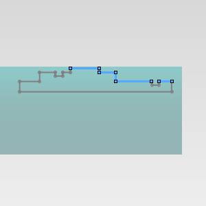
Spun Profile
This section appears when the Spun Profile method is selected for the Feature Extraction Method.
-
Arc Fit - creates arcs as the extracted geometry where possible based
on the tolerance selected. Arc Fit - creates only lines as the extracted geometry.
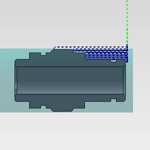
Feature Refinement
Regardless of the extraction method used, the Feature Refinement section will be available and allows you to exclude geometry which might be better suited to facing and cut off operations. These options are not needed when selecting geometry for a groove feature.
-
Remove first vertical
line - removes the first vertical
line (front face) from the detected feature geometry. Remove first vertical
line - keeps the first vertical
line (front face) from the detected feature geometry and incorporates it into the feature.
-
Remove last vertical
line - removes the last vertical
line (back face) from the detected feature geometry. Remove last vertical
line - keeps the last vertical
line (front face) from the detected feature geometry and incorporates it into the feature.
Next Topic
After assigning geometry to the feature, click Next> > to go to Feature Parameters.