


 Parameters
Introduction
This topic explains the Parameters page of the Advanced Planar operation found in the 3 Axis Wizard.
 Parameters
Finish
Stepover
-
 Standard - This option creates
a standard stepover based on Stepover value.
Standard - This option creates
a standard stepover based on Stepover value.- Stepover
- defines the distance between each pass in X and Y, or the XY plane.

- Stepover
- defines the distance between each pass in X and Y, or the XY plane.
-
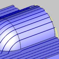
 Adaptive- The adaptive stepover
is similar to the standard stepover, except that it creates additional
passes in steep areas of the feature based on the defined Stepover and
Minimum Stepover values. This creates a more consistent finish in steep
areas by eliminating significant height changes from one pass to the next.
Adaptive- The adaptive stepover
is similar to the standard stepover, except that it creates additional
passes in steep areas of the feature based on the defined Stepover and
Minimum Stepover values. This creates a more consistent finish in steep
areas by eliminating significant height changes from one pass to the next.- Stepover
- defines the distance between each pass in X and Y, or the XY
plane.
- Minimum
Stepover - determines the minimum distance between adjacent
slices for the Adaptive Stepover passes.
-
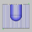
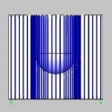
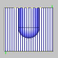
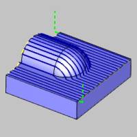
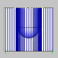
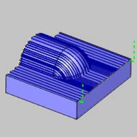
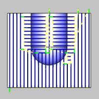
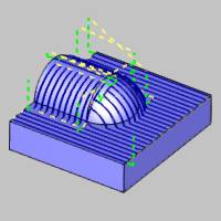
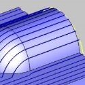
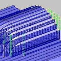
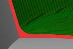
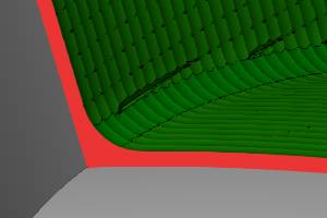
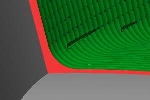
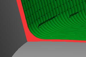
Trim adaptive passes - when this option is selected, the Adaptive result is trimmed to the remove excessive cuts from areas they are not needed. Click on the images below to see each in action
 - Clear the check box to turn off the Trim adaptive passes.
 - Select the check box to turn on Trim adaptive passes. This localizes the adaptive cut to the areas in which it is required. Trim adaptive passes
Trim adaptive passes
- Select the check box to turn on Trim adaptive passes. This localizes the adaptive cut to the areas in which it is required. Trim adaptive passes
Trim adaptive passes


- Stepover
- defines the distance between each pass in X and Y, or the XY
plane.
-
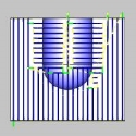
Perpendicular - This option creates opposing (perpendicular)
passes when the height change between toolpath slices exceeds the specified
threshold value. This helps provide a better finish for steep areas of
the feature using the Stepover, Pass Extension, and Threshold Distance
parameters.Stepover
- defines the distance between each pass in X and Y, or the XY plane.
- Stepover
- defines the distance between each pass in X and Y, or the XY plane.
- Pass
Extension - adds the specified distance to the perpendicular
passes of the toolpath to help blend the transition between the
perpendicular cutting directions.
- Threshold
Distance - determines the maximum allowable height change
from one toolpath pass to the next before perpendicular passes
are created.

- Stepover
- defines the distance between each pass in X and Y, or the XY plane.
- Machining
Tolerance - the amount of variation allowed for creating the
toolpath for the feature. The accuracy of the toolpath does not exceed
this range.
-
Cut Holes - extends the toolpath into any holes
that may be present in the surface.
-
Ignore Holes - does not place the toolpath into any
holes and treats the surface as if it is continuous and unbroken.
Depth Options
- Top of Job
- sets the highest Z location for toolpath
as the top of stock. -
allow you to specify the highest Z location for toolpath in this operation.
Select the check box and type a value to define a plane for the top
of job.- Pick - hides the Wizard to allow
you to set the Top of Job by selecting geometry whose height, in relation to the machine setup, is at the desired value.
- Pick - hides the Wizard to allow
you to set the Top of Job by selecting geometry whose height, in relation to the machine setup, is at the desired value.
- Bottom of Job
- sets the lowest Z location for
toolpath as the bottom of stock. -
allows you to specify the lowest Z location for toolpath in this operation.
Select the check box and type a value to define a plane for the bottom
of job.- Pick - hides the Wizard to allow you to set the Top of Job by selecting geometry whose height, in relation to the machine setup, is at the desired value.
Note: The Bottom of Job and Top of Job values are in reference to the machining origin (Machine Setup coordinate) of the part.
- Multiple
Passes on Full Width Cut
- Clear the check box to turn off Multiple Passes on Full Width Cut.
- Select the check box to turn on Multiple Passes on Full Width Cut and
the Depth Step parameter. This helps the operation to cut steep areas
of the model better by adding more cuts when the depth between two passes
is greater than the stepover amount.- Depth
Step - determines the depth of cut for extra passes created
using Multiple Passes on Full Width Cut.
- Depth
Step - determines the depth of cut for extra passes created
using Multiple Passes on Full Width Cut.

- Step
Down
- Clear the check box to turn off Multiple Passes on Full Width Cut.
- Select the check box to turn on Multiple Passes on Full Width Cut and
the Depth Step parameter. This helps the operation to cut steep areas
of the model better by adding more cuts when the depth between two passes
is greater than the stepover amount.- Number of Passes - sets the number of additional
passes to create.
- Depth
Step - determines the spacing between the extra passes
created.
- Sort by
- Slices
- cuts all depths on one pass before moving to the
next pass.
- Passes - cuts the first depth on all passes before coming back to cut the second depth.
- Slices
- cuts all depths on one pass before moving to the
next pass.
- Number of Passes - sets the number of additional
passes to create.
Allowance
The Allowance settings are used to define the rest material, or the amount of material remaining after this operation to be removed by the next operation, in one of two ways. These options offset the model geometry to calculate the toolpath. You can use positive or negative values to leave extra material or cut deeper than the model geometry, respectively.
Offset Type
The Offset Type determines if the allowance is applied to the entire model or separately for the bottom and sides of the part. Select one of the following options and then type the allowance value in the available allowance boxes.
- Global
- applies a single allowance value to the entire model using the Allowance
XYZ value.
- Allowance
XYZ - is the amount of material left on the entire model
(XYZ).

- Side
and Bottom - allows you to specify separate allowances for
the side (XY) and bottom (Z) of the part.
- Side
Allowance - is the amount of material left on the sides
of the part (XY).
- Bottom
Allowance - is the amount of material left on the bottom
of the part (Z).
- Advanced - opens the Allowances dialog to allow you to select surfaces to assign as either Part, or Fixture, geometry items. Each of those items can then have specific allowances set. - With this check box cleared, only the Offset Type and Allowance above will be used for the Feature Geometry.
- With this check box selected, the geometry and allowances set in the (Advanced) Allowances dialog will be active.
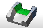
Bounds
The Trim to Stock option provides the ability to pass the stock definition to the toolpath calculation, which trims the toolpath to remove air cutting. You can assign stock geometry (.stl or solid model) to the Operation Stock item in the CAM Tree, or if you do not assign operation stock, the software uses the stock definition from the Stock Wizard. This option can be used as a 3D boundary for the operation.
Important: In order to pass a stock definition to the toolpath calculation, you must turn on Trim to Stock in the wizard as explained next. If you assign Operation Stock, but do not turn on Trim to Stock, the stock isn't used in the toolpath calculation.
- Trim to
Stock
- Clear the check box to create the operation without trimming the toolpath
to the stock. - Select the check box when you want the software to trim the toolpath for
the operation to the stock in one of two ways. You can (1) assign a solid
model or .stl file using the Operation Stock item in the CAM Tree, or
(2) if you don't assign operation stock, the software automatically uses
the stock from the Stock Wizard to trim the toolpath. View Selecting
Operation Stock.


Tip: You
can use simulation to save the stock model as an .stl file, which can
then be used as Operation Stock. To learn more, view How
to Save Simulation Stock as STL.