


Part definition: Multiaxis Machining
Introduction
This topic will explain the options found in the Part definition tab of the Multiaxis Machining operation.
Part definition
The Part definition tab allows you to define the part, the stock to be left, as well as the surface quality.
Part Definition
-
Part surfaces - click
 to enable selection mode and select the part surfaces.
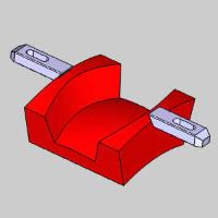
-
Floor surfaces - click
to enable selection mode and select the floor surface(s).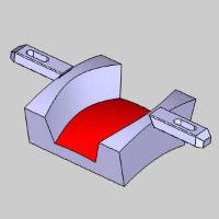
-
Stock to leave - is the amount of material that remains on the surface (for finishing).
-
Wall surfaces - click
to enable selection mode and select the wall surface(s). This should be the entire part, but do not include a ceiling surface.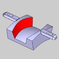
-
Stock to leave - is the amount of material that remains on the surface (for finishing).
-
-
Ceiling surfaces - only used with the strategies (Surface Paths page): Offset From Ceiling and Morph Between Ceiling and Floor. Click
to enable selection mode and select the ceiling surface(s).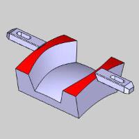
-
Fixture surfaces - only used with the Roughing Machining Pattern strategy. Click
to enable selection mode and select the fixture surface(s) to be avoided during toolpath calculation.
-
Stock to leave - is the distance to keep away from the selected fixture geometry.
-
Surface Quality
-
Cut tolerance - type a value to define how accurate the toolpath is in relation to the selected geometry. Smaller values create a more accurate toolpath but also increase calculation times.
Tip: You can reduce the cut tolerance value, for example from 0.0005 to 0.005, to speed up the toolpath calculation while creating and modifying your toolpath. Once you're are happy with the result, you can then set it back to the original tolerance to calculate the toolpath before posting the output.