


Part definition: Turn Mill
Introduction
This topic will explain the options found in the Part definition tab of the Turn Mill operation.
Part definition
The Part definition tab allows you to select the required geometry for the feature, define the part and any check surfaces. This tab also allows you to determine how much of the part is machined and in which direction, as well as the machining tolerance of the created toolpath.
Part Definition
-
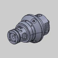
Part - defined the geometry with either:
-
Turn profile - allows you to select wireframe geometry for the operation. This is spun into a 3D model to utilize as the geometry of the operation. Click
 to open the Re/Select Geometry dialog.
-
Part surface - allows you to select a model for the geometry. If the model is not symmetric it is the spun into a symmetric model to use as the geometry of the operation. Click
to open the Re/Select Geometry dialog.
-
Stock to leave - is the amount of material that remains on the surface (for finishing).
-
-
Axis of rotation - launches the Rotation axis dialog allowing you to define the axis of rotation. By default the main rotation axis is set to Z.
Rotation axis
-
 By start point and end point - allows you to either enter values for the start and end points, or select a line to define those points.
 -
 By base point and direction - allows you to specify a direction in which the area will be limited.
-
Base point - Select between Center to use the center of the geometry of a User defined point.
-
Direction - Select between User defined direction or standard X,Y,Z axes in order to define the direction of limitation.
-
-
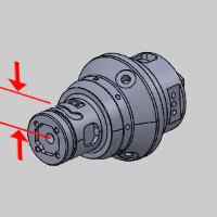
Machining area - launches the Machining area dialog allowing you to define a machining range in the radial and axial directions.
Machining area
Machining area
-
Area from - is locked to All input geometry.
User limits
For each option, you can enter start and end values in reference to the machining setup, or select the ellipses button to enter the start and end locations manually. In the subsequent dialog you can also enter the Re/Select Geometry dialog to select a line or two points to define the start and end locations.
- Axial - select the check box to define the start and end of the machining area along the axial distance.
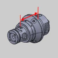
- Radial - select the check box to define the start and end of the machining area along the radial distance.
- Stock definition - launches the Stock definition parameter dialog to allow you to define the stock for the operation.
Stock Definition Parameters
-
Stock surfaces - allows you to launch a dialog in order to select geometry to represent the stock to be removed. Choose between selecting a solid body, or selecting an stl file.
-
Shrink- select this option and type a value used to shrink the defined stock geometry.
-
Expand- select this option and type a value used to expand the defined stock geometry.
Note: The Shrink and Expand values offset the stock geometry in all three directions.
Surface quality
-
Cut tolerance - type a value to define how accurate the toolpath is in relation to the selected geometry. Smaller values create a more accurate toolpath but also increase calculation times.
Tip: You can reduce the cut tolerance value, for example from 0.0005 to 0.005, to speed up the toolpath calculation while creating and modifying your toolpath. Once you are happy with the result, you can then set it back to the original tolerance to calculate the toolpath before posting the output.
- Max. point distance
 - Select the check box to use the value specified as the maximum distance between toolpath points.
 - Clear the check box to turn off this option.
 - Max. angle step
- Select the check box to use the value specified as the maximum angle difference between toolpath points. - Clear the check box to turn off this option.