


Pig Art Emboss Tutorial
Introduction
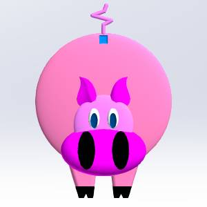
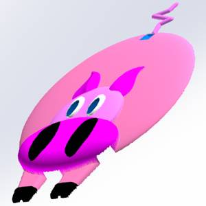
This tutorial is designed to help you become familiar with the BobARTEmboss features.The Emboss Regular, Emboss Swept, and Emboss 2-Rail Sweepfeatures are used to create a piggy-bankBobART model.Follow this tutorial along with the other Emboss tutorialsto learn more about the BobART Emboss features.
Example File
If you are connected to the Internet, the part file for this example can be downloaded automatically by clicking the following link: Pig Art EmbossExample.sldprt
Once you download and saved the zip file, extract the files on your system in an easy place to remember.You can then open the file to use with this tutorial.All files for the tutorials in this help system available for download can be found by clicking on the following link: http://www.bobcad.com/helpfiles.
Part 1) Open the Example File
-
in the File menu, click Open.
The Open dialog is displayed. -
Select the folder in which you saved theexample file.
-
Select PigArt Emboss.
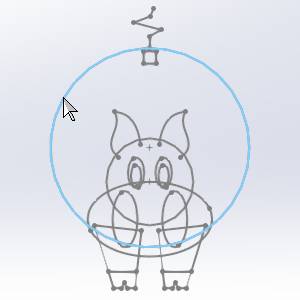
The file is opened and the geometry is displayedin the graphics area.
Part 2) Define the Canvas
-
In the
 BobART Manager tab, right-click
  EmbossModel, and click Create/Modify Canvas.
The Canvas Definition dialog opens. -
By default the UCS is set to
-
In the ModelSize group, set the Xvalue to 9.00, and set theY value to 12.00.
Note: The resolution updates automatically as the size is updated.The Resolution will improve the quality of the model, but also increase the size of the file, and the amount of time it takes to regenerate the surface.
The image on the left shows stock with a resolution of 25, while the image on the right shows stock with a resolution of 150.
Normally, since ultra fine details will not be visible on the final machined part, a higher resolution stock is not really needed.However, if it is wanted, wait until the model is complete and adjust the resolution at the end.This will keep regeneration times low during the creation of the model.
-
At this point, as an option, you can also select the Remove Non-Emboss Area check box.
This will remove any area of the canvas that is not being utilized by a BobArt feature. -
Click OK.
The canvas appears in the graphics area. -
Click Cancel.
The Canvas Definition dialog disappears.
Part 3) Regular Emboss 1 - Body
Create the feature and set Attributes
-
In the
 BobART Manager tab, right-click EmbossModel, and click Emboss Regular.
The Emboss Regular dialog opens. -
For the Name, add Body to the front of the text so our feature name reads Body Regular Emboss 1.
-
Click the drop down next to Color,and select More Colors....
The Select Color dialog appears. -
In the vertical color spectrum bar, click on the pink area, or you can use R 250, G 125, B 200 values, then click OK.
The Select Color dialog disappears and the color is set to pink.
By default the Application Type is set to Add and the Selected Geometry list has focus.
Select Geometry
-
In the graphics area,select the geometry that represents the body of the pig as shown next.
The geometry is added to the Selected Geometry list.
Define the Cross-Section
-
Click theCross-Section option to access the drop down list, and select ConvexEllipse.
-
Set the X Axis Radius value to4.00.
-
Set the Y Axis Radius value to 0.50.
-
Click OK.
The body is now embossed and appears as shown next.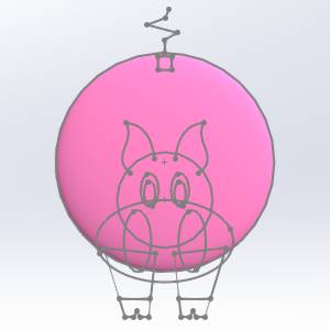
-
Click Cancel to exit the dialog.
Part 4) Regular Emboss 2 - Nose
Create the feature and set Attributes
-
In the
BobART Manager tab, right-click EmbossModel, and click Emboss Regular.
The Emboss Regular dialog opens. -
For the Name, add Nose to the front of the text so our feature name reads Nose Regular Emboss 2.
-
Click the drop down next to Color,and select More Colors....
The Select Color dialog appears. -
In the vertical color spectrum bar, click on the darker pink area, or you can use R 255, G 0, B 255 values, then click OK.
The Select Color dialog disappears and the color is set to pink. -
Set the Application Type to Merge High.
Select Geometry
-
In the graphics area,select the geometry that represents the nose of the pig as shown next.
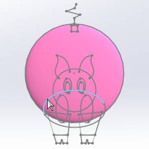
The geometry is added to the Selected Geometry list.
Define the Cross-Section
-
With Convex Ellipse still selected as the Cross-Section, set the X Axis Radius value to0.750.
Leave the Y Axis Radius value at0.500. -
Click OK to update the canvas.
The nose is now embossed and appears as shown next.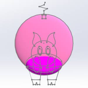
For comparison, an image of the same feature isshown using the Add application type as mentioned previously.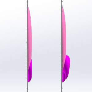
-
Click Cancel to exit the dialog.
Note: Most,but not all of the nose geometry overlaps the body geometry.Merge Highis used to create the nose with one consistent height.If the Add applicationtype is used, then the area of the nose that does not overlap the bodygeometry would not be the same height as the rest of the nose (this isshown at the end of Part 3).Merge High leaves only the highest area ofintersection between two embossed features.
Tip: To hideor show the stock,
Part 5) Regular Emboss 3 - Face
Create the feature and set Attributes
-
In the
BobART Manager tab, right-click EmbossModel, and click Emboss Regular.
The Emboss Regular dialog opens. -
For the Name, add Face to the front of the text so our feature name reads Face Regular Emboss 3.
-
Click the drop down next to Color,and select More Colors....
The Select Color dialog appears. -
In the vertical color spectrum bar, click on a slightly different pink area, or you can use R 255, G 128, B 192 values, then click OK.
The Select Color dialog disappears and the color is set to pink. -
The Application Type should still be set to Merge High which is what we want for this part.
Select Geometry
-
In the graphics area,select the geometry that represents the face of the pig as shown next.

The geometry is added to the Selected Geometry list.
Define the Cross-Section
-
Click theCross Section still set to Convex Ellipse, update the X Axis Radius value to 1.000.
-
Set the Y Axis Radius to0.250.
-
Click OK.
Notice that the face emboss does not show.This is because the heightof the body is greater than the height of the face, and the MergeHigh application type is used.
Update the Base Height
-
In the Base Height field, enter0.500.
This adds a -
Click OK.

The result should look as follows.
Notice that the face now covers the nose.This is not the desired result either.To resolve this issue you add a baseheight to the previous nose emboss operation as well. -
Click Cancel.
Update the Nose Regular Emboss 2 - Merge High feature
-
Right-click Nose RegularEmboss 2 - Merge High, and click Edit.
The Emboss Regular dialog opens. -
In the Base Height field, type0.375.
This adds a -
Click OK.

The model should appear as follows. -
Click Cancel.
Part 6) Regular Emboss 4 - Nostrils
Create the feature and set Attributes
-
In the
BobART Manager tab, right-click EmbossModel, and click Emboss Regular.
The Emboss Regular dialog opens. -
For the Name, add Nostrils to the front of the text so our feature name reads Nostrils Regular Emboss 4.
-
Click the drop down next to Color,and select Black.
-
Set the Application Type to Subtract.
Select Geometry
-
In the graphics area,select the geometry that represents the face of the pig as shown next.

The geometry is added to the Selected Geometry list.
Define the Cross-Section
-
Set the Cross-Section to Convex ARC.
-
Set the Radius value to0.250.
-
In the Start Anglefield, enter 60.00.
-
Confirm the EndAngle is set to 90.00.
Update the Base Height
-
Set the Base Height to 0.00.
-
Click OK.
Tip: Noticethat the Start Angle is changed to 60 degrees, instead of 0 degrees.Theembossed model now starts 60 degrees into the defined Cross Section.Theresult is that the edge of the model has a more gradual slope in relationto the stock.The following image shows two identical Regular Emboss featureswith the first starting at 0 degrees, and the second starting at 60 degrees.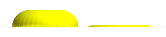
It is important to explore the various settingsof the Emboss features.Changing one setting can create a substantialdifference in the result.By experimenting with the different settings,you can find multiple ways to accomplish the same task, with variationsin the result.Knowing these variations helps you greatly when creatingembossed models.
- Click Cancel to exit the dialog.
Part 7) Regular Emboss 5 - Legs
Create the feature and set Attributes
-
Right-click
EmbossModel, and click Emboss Regular.
The Emboss dialog opens. -
For the Name, add Legs to the front of the text so our feature name reads Legs Regular Emboss 5.
-
Click the drop down next to Color,and select the pink we used for the body in the Recent Colors area.
-
Under ApplicationType, click Merge High.
Select Geometry
Define the Cross-Section
-
Leave the Cross-Section set to Convex Arc with a 0.250 radius, but update the Start Angle value to 0.00.
Leave the End Angle at 90.00. -
Click OK.
-
Click Cancel.
Part 8) Regular Emboss 6 - Feet
Create the feature and set Attributes
-
Right-click
EmbossModel, and click Emboss Regular.
The Emboss dialog opens. -
For the Name, add Feet to the front of the text so our feature name reads Feet Regular Emboss 6.
-
Click the drop down next to Color,and select Black.
The Color is set to black. -
Under ApplicationType, click Add.
Select Geometry
-
In the graphics area,select the geometry that represents the feet of the pig as shown next.

Define the Cross-Section
-
Leave the Cross-Section set to Convex Arc, but update the Radius value to0.100.
Leave the Start Angle at 0.00 and the End Angle at 90.00. -
Click OK.
The result should look like next image.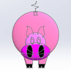
-
Click Cancel.
Part 9) Regular Emboss 7 - Eyes
Create the feature and set Attributes
-
Right-click
EmbossModel, and click Emboss Regular.
The Emboss dialog opens. -
For the Name, add Eyes to the front of the text so our feature name reads Eyes Regular Emboss 7.
-
Click the drop down next to Color,and select White.
The Color is set to white. -
Under ApplicationType, click Merge High.
Select Geometry
-
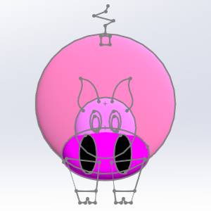
In the graphics area,select the geometry that represents the eyes of the pig as shown next.


Define the Cross-Section
-
Leave the Cross-Section set to Convex Arc but update the Radius value to0.125.
Leave the Start/End Angles at their current values.
Set the Base Height
-
In the Fast Edit section, update the Base Height to
-
Click OK.
The result should look like the previous image. -
Click Cancel.
Part 10) Regular Emboss 8 - Pupils
Create the feature and set Attributes
-
Right-click
EmbossModel, and click Emboss Regular.
The Emboss dialog opens. -
For the Name, add Pupils to the front of the text so our feature name reads Pupils Regular Emboss 8.
-
Click the drop down next to Color,and select Blue.
The Color is set to blue. -
Set the ApplicationType to Subtract.
Select Geometry
-
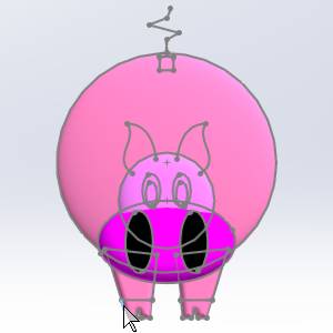
In the graphics area,select the geometry that represents the pupils of the pig as shown next.


Define the Cross-Section
-
We will be using all the same values in the Cross-Section section.
Update the Base Height
-
Set the Base Height value to 0.00.
-
Click OK.

The result should look like the previous image. -
Click Cancel.
Part 11) Regular Emboss 9 - Coin Slot
Create the feature and set Attributes
-
Right-click
EmbossModel, and click Emboss Regular.
The Emboss dialog opens. -
For the Name, add Coin Slot to the front of the text so our feature name reads Coin Slot Regular Emboss 9.
-
Click the drop down next to Color,and select Light Blue.
The Color is set to light blue. -
Leave the Application Type set to Subtract.
Select Geometry
-
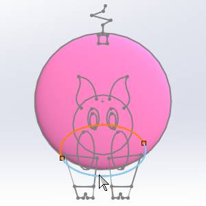
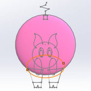
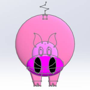
In the graphics area,select the geometry that represents the coin slot on the pig as shown next.


Define the Cross-Section
-
For this feature we use the same Cross-Section values once more.
Click OK.
-
Click Cancel.
Part 12) Swept Emboss 10 - Tail
Create the feature and set Attributes
-
Right-click
EmbossModel, and click Emboss Swept.
The Emboss dialog opens. -
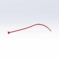
For the Name, add Tail to the front of the text so our feature name reads Tail Swept 10.
-
Click the drop down next to Color,and select the pink used for the nose in the Recent colors group.
The Color is set to pink. -
Set the ApplicationType to Merge High.
Select Geometry
-
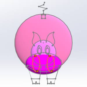
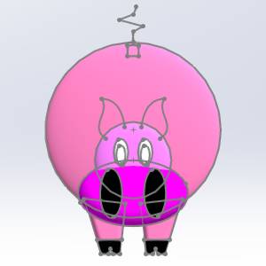
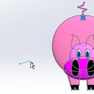
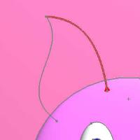
In the graphics area,select the geometry that represents the tail of the pig as shown next.

Tip: Noticethat the tail geometry is not a closed entity.This is why the EmbossSwept feature is used.The Emboss Swept feature allows the use of openor closed feature geometry, and it creates an emboss using the geometryas the center line for the feature.
Define the Cross-Section
- The same values are used in the Cross-Section section.
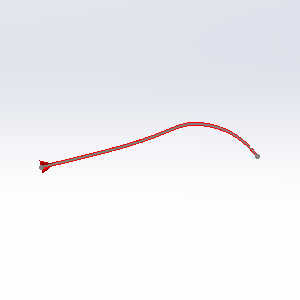
Click OK.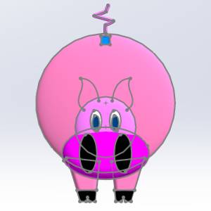
-
Click Cancel.
At this point, the feature tree is becoming ratherlarge.You may want to collapse a few of the features to save space inthe BobART Tree.To collapse the features, click the icon next to each feature name.
Part 13) Emboss 2-Rail Sweep 11 - Right Ear
Create the feature and set Attributes
-
Right-click
EmbossModel, and click Emboss 2Rail Sweep.
The Emboss dialog opens. -
For the Name, add Right Ear to the front of the text so our feature name reads Right Ear 2 Rail Sweep 11.
-
Click the drop down next to Color,and select More Colors....
The Select Color dialog appears. -
In the vertical color spectrum bar, click on the darker pink area, or you can use R 255, G 0, B 255 values, then click OK.
The Select Color dialog disappears and the color is set to pink. -
Set the ApplicationType to Merge High.
Select Geometry
-
Rail 1 : By default, the Selected Geometry list in the Rail 1 group has focus.
-
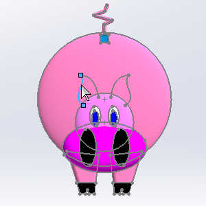
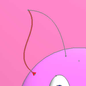
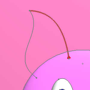
In the graphics area,select the geometry that represents the outer edge of the pig's rightear as follows.
-
Click in the Profile Chains list to ensure the direction points up away from thepig's face as shown in the image below.
-
Click the Reverse Direction button as needed.
The effect this direction can have on the end result can be viewed in the table at the end of this section.
-
-
Rail 2
-
In the Rail 2 group, click in the Selected Geometry list so it has focus.
-
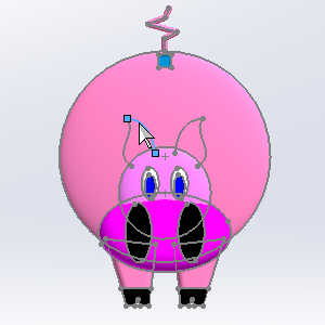
In the graphics area,select the geometry that represents the inner edge of the pig's rightear as follows.
-
Click in the Profile Chains list to ensure the direction points up away from thepig's face as shown in the image below.
-
Click the Reverse Direction button as needed.
-
-
Cross-Section
-
Click in the Selected Geometry list in the Cross-Section group.
-
Select the geometry to the left of the canvas.
-
Click on the Profile Chain and ensure the direction is to the right.
The effect this direction can have on the end result can be viewed in the table at the end of this section. -
Click the Reverse Direction button as needed.
-
Set the Base Height and update the canvas.
-
In the BaseHeight field, type 0.500.
-
Click OK.
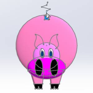
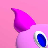
The result should look like next image.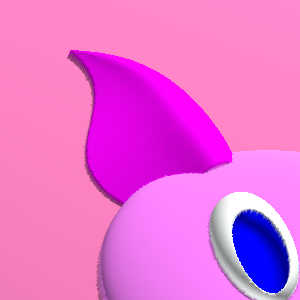
-
Click Cancel.
| Rail 1 direction | Rail 2 direction | Cross-Section direction | Result |

|
|
|

|
| When both rails point in the same direction, rather than opposing directions, the result can be adjusted with the direction of the Cross-Section.Notice the result above with the Cross-Section direction pointing to the right. | |||
|
|
|
|
|
| Now notice the result with the Cross-Section pointing to the left. | |||
|
|

|
|

|
| The results with rails in opposing directions will normally be unwanted regardless of the Cross-Section direction. | |||
Part 14) Emboss 2-Rail Sweep 12 - Left Ear
Insert and Edit the Feature
-
Right-click
EmbossModel, and click Emboss 2Rail Sweep.
The Emboss dialog opens. -
For the Name, add Left Ear to the front of the text so our feature name reads Left Ear Regular Sweep 12.
Set the color and application type
-
For this feature we use the same color and Application Type.
Set the geometry
-
Repeat the same steps used for the previous ear.
Use the outer ear entity as the first railand the inner ear entity as the second rail.The cross section geometrydirection is the same as for the right ear.
Important: Be sure the direction of the profiles chains matches what was used for the previous feature.
Set the Base Height and update the canvas.
- We use the same Base Height as in the last feature.
Click OK.
The result should match that in the image above. -
Click Cancel.
Part 15) Update the Canvas Resolution
-
Now right-click
EmbossModel, click Create/ModifyCanvas. -
In the Resolutionfield, type 150.
-
Click OK.
This improves the appearance of the embossed model. -
Click Cancel to close thedialog.
This concludes the tutorial.