


How to Create a Machine
Introduction
This tutorial explains how to create a machine, and will provide links to related topics.
Machine Creation
Machine creation startswith a machine definition to define each element of the machine, suchas the linear and rotary axes.Then the parameters are defined for eachelement of the machine, such as the moving direction and limits.The parametervalues defined in the Machine Definition are used when you create NC programs(G-code).For each element, geometry (.stl) files are added to definewhat appears in the simulation window.The geometry should only be addedif you have Pro Simulation which includes the full machine simulation.The Standard Simulation does not include the full machine simulation,so the geometry files are not used.The Machine Definition must be createdregardless of the simulation level.(The Pro Simulation/full machine simulationis only included with the 4 Axis Pro, 5 Axis Standard, or 5 Axis Pro modules.)
The following shows the Machine Definition tree that defines the 4-axismachine that is created in this example.
|
TheMachine Definition Tree |
Machine |
|
|
|
Notice the structure of the machine tree and the machine elements.Whenbuilding a machine, you must examine how the machine is built.For anymachine configuration, you can think of the machine as having a base.The base is the foundation upon which the machine is built.Every machineelement is attached to the base or to some other machine element.Therelationship of all of the machine elements, how they are connected, andin which way they move, defines how the machine is built.
The first tree item, ![]() Machine, islabeled with the machine name.This tree element can be thought of as the machine base.This is the startingpoint for building the machine.The next machine element to define isan element that is connected directly to the base.
Machine, islabeled with the machine name.This tree element can be thought of as the machine base.This is the startingpoint for building the machine.The next machine element to define isan element that is connected directly to the base.
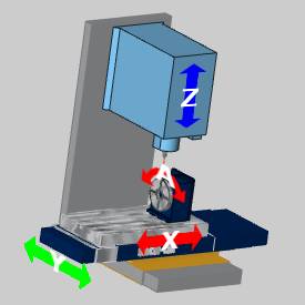
For this example, the next element defined in the tree is the linearY-axis.This is done because it is attached to the machine base.The nextmachine element is the linear X-axis which is attached to, and carriedby, the Y-axis element.The rotary A-axis elements are then attached to,and carried by, the X-axis element (table).The rotary table of the A-axisholds the workpiece which is the last tree item for this part/branch ofthe tree.
The Z-axis is separate from the elements attached to Y-axis becauseit is also attached directly to the machine base.The Z-axis element (spindle)holds the tool holder which holds the tool.You can see this structurein the machine definition tree.Notice that the Y-axis and Z-axis itemsare at the same position/priority in the tree (far left).
Steps:
Part 1) Add a New Machine
- In the CAM Tree,right-click CAM Defaults,and click Current Settings.
The Current Settings dialog appears.
The default page, Machine Parameters, should be active.
- In the Machinegroup, click Add.
The Add/Modify Machine dialog appears. - In the Add/ModifyMachine dialog, next to MachineName, type the name of the machine: 4Axis Example.
Next to Type, click the arrow,and select Milling. - Next to Axes,click the arrow, and select 4 AxisMachine.
For all machine types exceptlathe, the selection made here automatically creates a template forthe machine in the Machine Definition.When User Defined is selected,the Machine Definition tree is left empty for you to manually createall machine elements.(The Lathe Machine Definition is currently predefined.) - To close the dialog box and add the new machine, clickOK.
The Make list now shows thenew machine is selected, and the Numberof Axes box should display the number 4. - In the Machine Parametersgroup, define the parameters for your machine.
Part 2) Locating the Machine Definition Files
- When you create a new machine, a folder isautomatically created along with an XML file of the machine definition,in the BobCAD-CAM Data folder.The default location is: C:\BobCAD-CAMData\*Current Version*\MachSim\MachineName....This is the same location in which the geometry filesfor the machine must be stored.
- For the purposes of this tutorial, the nextstep is to copy the geometry files from the default machine that isprovided by BobCAM.
- Open the following folder: C:\BobCAD-CAMData\*Current Version*\MachSim.
Notice the folder named 4 Axis Examplehas been automatically created.
If you open the folder, you will see the 4Axis Example.xml file that stores all of the machine information. - Open the BC_4x_Millfolder, and select all of the files except the .xmlfile.Press CTRL+C to copythe selected files.
- Open the 4Axis Example folder and press CTRL+Vto paste the copied files into the folder.
These files are now available to add to theMachine Definition.
Important: Whenbuilding your own machine, you must place the .stl files for your machinein the folder that is created by the software as explained in the previoussteps.
Part 3) The Machine Definition Dialog Box - Define the Y-Axis Parameters
- On the left side of the CurrentSettings dialog box, click MachineDefinition.Notice the Machinegroup in the middle of the dialog.The machine tree shows allof the machine elements that have been automatically created.Thisdefinition includes the linear axes, the rotational axis, and thedynamic holder and workpiece elements.
- The items in the tree are used to defineor modify the parameters of each component.For example, in the tree,click
 Y.Notice on the right, in the MachineData group, the parameters for the Y-axis display.
Warning: When updating the ID of an axis, do not use spaces or numbers.If you would like to set Y to an ID of Y 1, you would need to enter Y_one to avoid spaces and numerals.
- The Direction and the Limits for the Y-axismust be defined.The machine being built requires the vector to benegative.Confirm that the Directionvector values are X0, Y-1, Z0.
Note: The vectordirection for the axes is determined by the type of machine.For machinesin which the table (and not the head) moves in X and Y, generally these valuesare negative.For machines where the head (tool) moves in X and Y, generallythese values are positive.The direction is determined by the relationshipof the machine elements and which way they need to move to make the toolmove in a positive direction in each of the X, Y, and Z axes.
- Under Limits, to theright of Min, click in thebox, and type the distance that this machine element can move alongthe defined direction.For this example, type -10.This defines 10 inches of travel in the negative Y-axis direction.

|

|
|
AllElements at Zero |
NegativeY-axis Limit |
- To the right of Maxvalue, click in the box and define the maximum distance that the elementcan move along the defined direction.For this example, type 10.This defines 10 inches of travelin the positive Y-axis direction.
|
|

|
|
AllElements at Zero |
PositiveY-axis Limit |
-
Set the Initial Valuefor this element to represent the elements starting position.Forthis example, type 0.
This sets the initial position to the originor zero location of the Y-axis.
Tip: Youcan utilize one of two methods when setting the X-axis, Y-axis, and Z-axislimits for 3-axis and 4-axis machines.In the first method you set thelimits to accurately reflect the real machine.In this scenario you mustproperly define the Work Offset to place the part within the machine limits.Otherwise, the posting engine can fail due to the exceeded limits.Youcould, instead, use the second method of setting very large limits in orderto not allow the posting engine to detect exceeded machine limits.
Part 4) Define the X-Axis Parameters
- In the Machinegroup, click X to select the linear X-axis.Inthe Machine Data group, nextto X, confirm the value is-1.
Again, this defines that the X-axis elements must move in the negativeX-axis direction in order to cause the tool to move in the positivedirection in reference to the part. - Under Limits,next to Min, click in thebox, and type -29.
This value defines 29 inches of travel inthe negative X-axis direction.
|
|

|
|
AllElements at Zero |
NegativeX-axis Limit |
- Next to Max, click inthe box, and type 11.
|
|

|
|
AllElements at Zero |
PositiveX-axis Limit |
-
Next to Initial Value,click in the box, and type 0.
Part 5) Define the A-Axis Parameters
- In the Machinegroup, click
 A to select the rotary A-axis.Inthe Machine Data group, noticethat the Direction is definedas X1, Y0, Z0.This defines rotationaround the X-axis.
 - Notice that the Centerpointis defined as X0, Y0, Z0.
This defines the center point of rotation in reference to the machinezero, which for this machine is the center of the front face of therotary platter.Because the geometry was aligned to the zero of thereference point, this distance is zero. - The next step is to define the rotary limits.Under Limits, next to Min, click in the box and type -100,000.
You must set this value to the degrees of rotation supported by themachine. - Next toMax, click in the box and type 100,000.
- Next to InitialValue, click in the box and type 0.
Part 6) Define the Z-Axis Parameters
- In the Machinegroup, click Z to select the linear Z-axis.Inthe Machine Data group, noticethat the Direction is definedas X0, Y0, Z1.This defines movementalong the Z-axis.
- Under Limits,next to Min, click in thebox and type -7.
|
|

|
|
AllElements at Zero |
NegativeZ-axis Limit |
- Next to Max, click inthe box and type 18.
|
|

|
|
AllElements at Zero |
PositiveZ-axis Limit |
-
Next to Initial Value,click in the box and type 18.
Adding Geometry to the Machine Definition (Pro Simulation Only)
Important: ThePro Simulation is included with the 4 Axis Pro, 5 Axis Standard, or 5Axis Pro modules.If you do not have Pro Simulation, donot add geometry as shown in Parts 7-11 of this tutorial.The StandardSimulation does not include the full machine simulation, so it does notuse the geometry files for simulation.
The following image shows all of the individualgeometry files (.stl), togetherin one Workspace.This is shown to help you understand how each geometryitem is aligned in the graphics area when creating the geometry filesfor the machine.In the second image, the view is made transparent andzoomed in to show the coordinate system used to align the machine elements.


After adding all of the geometry files tothe machine definition in the following steps, the Machine tree lookssimilar to the following.
![]() 4 Axis Machine
4 Axis Machine
![]()
![]() mh_base
mh_base
![]()
![]() Y
Y
![]()
![]()
![]() Y AxisBase
Y AxisBase
![]()
![]()
![]() X AxisBase
X AxisBase
![]()
![]()
![]() X
X
![]()
![]()
![]() Table
Table
![]()
![]()
![]() Rotary Base
Rotary Base
![]()
![]()
![]() A
A
![]()
![]()
![]() RotaryTable
RotaryTable
![]()
![]()
![]() WorkpieceTransform
WorkpieceTransform
![]()
![]() Z
Z
![]()
![]()
![]() Spindle
Spindle
![]()
![]()
![]() HolderTransform
HolderTransform
![]()
![]()
![]() Tool
Tool
![]()
![]() CC (Collision Check)
CC (Collision Check)
Part 7) Add the Machine Base Geometry
![]() 4 Axis Machine
4 Axis Machine
![]()
![]() mh_base
mh_base
When creating geometry, the files must be saved using the .stlfile extension.
- In the Machinegroup, right-click the top tree item
 4Axis Example, and click AddGeometry.
 - In the Opendialog box, navigate to the 4 AxisExample folder, and select BC_4x_Mill_Rot-X_Base.stl,and click Open.
- The geometry item is added to the tree.Inthe tree, click
 Geometry so it is selected.
In the Machine Data group,next to ID, click the name(geometry) and change the name to mh_Base.
Because the prefix (mh_) was added, the visibility of this item can bechanged using the machine housing view toggle in the simulation. - Notice the remaining parameters for the geometryitem in the Machine Data group.The parameters for the added geometrycan be modified from this location.For example, if you needed tochange the .stl file, in the left column click Geometry.Notice that the
 icon appears next to BC_4x_Mill_Rot-X_Base.stl.You can click todisplay the Open dialog boxand select a new geometry file.
For visual reference, the base geometry fileis shown next.

Part 8) Add the Y-Axis Geometry
![]()
![]() Y
Y
![]()
![]()
![]() Y AxisBase
Y AxisBase
![]()
![]()
![]() X AxisBase
X AxisBase
-
In the machine tree, right-click
Y,and click Add Geometry. - In the Opendialog box, select BC_4x_Mill_Rot-X_YAxis Base, and click Open.
- The geometry item is added to the tree.Inthe tree under Y, click Geometry so it is selected.
In the Machine Data group,next to ID, select the name(geometry) and type Y Axis Base.
Warning: While adding spaces is acceptable for geometry items, it is not acceptable for the axes themselves.Both spaces and numerals must be avoided when customizing the ID of the axes.If you would like to set X to an ID of X 1, you would need to enter X_one to avoid spaces and numerals.
- Click Color,and on the right, click .In the Color dialog box, selecta color for the element and click OK.
When you run simulation, the Y-axis basewill be shown with the selected color.
For visual reference, the Y-axis base geometry file is shown next.

- In the machine tree, right-click Y,and click Add Geometry.
- In the Open dialog box,select BC_4x_Mill_Rot-X_X Axis Base,and click Open.
- The geometry item is added to the tree.Click Geometry.
In the Machine Data group,next to ID, select the name(geometry) and type X Axis Base. - Set the color used for the base.
For visual reference, the X-axis base geometry file is shown next.

Part 9) Add the X-Axis Geometry
![]()
![]() X
X
![]()
![]()
![]() Table
Table
![]()
![]()
![]() Rotary Base
Rotary Base
- In the machine tree, right-click X,and click Add Geometry.
- In the Opendialog box, select BC_4x_Mill_Rot-X_Table,and click Open.
- The geometry item is added to the tree.ClickGeometry.
In the Machine Data group,next to ID, select the name(geometry) and type Table - Set the color for the element.
- Click ReflectMap, and on the right side, click .Inthe Open dialog box, selectthe TableReflection.bmp fileand click OK.
Image files used for the Reflect Map mustuse the .bmp file extension.
For visual reference, the (X-axis) table geometry file is shown next.

- In the machine tree, right-click X,and click Add Geometry.
- In the Open dialog box,select BC_4x_Mill_Rot-X_Rotary_Base,and click Open.
- The geometry item is added to the tree.Click Geometry.
In the Machine Data group,next to ID, select the name(geometry) and type Rotary Base. - Set the color for the rotary base.
For visual reference, the rotary base geometry file is shown next.

Part 10) Add the A-Axis Geometry
![]()
![]()
![]() A
A
![]()
![]()
![]() RotaryTable
RotaryTable
- In the machine tree, right-click A,and click Add Geometry.
- In the Opendialog box, select BC_4x_Mill_Rot-X_Rotary_Face,and click Open.
- The geometry item is added to the tree.ClickGeometry.
In the Machine Data group,next to ID, select the name(geometry) and type Rotary Table. -
Set the color for the element.
For visual reference, the rotary table geometry file is shown next.

Part 11) Add the Z-Axis Geometry
![]()
![]() Z
Z
![]()
![]()
![]() Spindle
Spindle
- In the machine tree, right-click Z,and click Add Geometry.
- In the Opendialog box, select BC_4x_Mill_Rot-X_ZAxis Spindle and click Open.
- The geometry item is added to the tree.ClickGeometry.
In the Machine Data group,next to ID, select the name(geometry) and type Spindle.
For visual reference, the spindle geometry file is shown next.

Part 12) About the Dynamic Elements
The dynamic elements are the elements that can change with each program.The Workpiece Transform contains the first set of dynamic elements inthe tree.This transform includes the toolpath, initial stock, stock,fixture, and the workpiece.Generally, you do not have to define geometryfor each of these items because they are defined by each program thatyou create.This is also true for the Holder Transform elements.Thesedynamic elements are automatically created in the tree for you when youcreate a new machine (except when using User Defined).The geometry forthe holder element in simulationis automatically defined using the assigned tool holder from the millingwizards.
|
|
|
- In the Machinegroup, under the
 Workpiece Transform, click
 Initial stock.
Notice the parameters in the MachineData group.As with the other geometry items, you can definea color for the element.It is helpful to define a different colorfor each element that appears in simulation. - In the MachineData group, next to Transparency,click in the box and change the value to 40.
This makes the initial stock item that is shown in simulation appearwith forty-percent transparency.When this item is fully visible,it will still appear slightly transparent which makes it easier totell it apart from the stock or workpiece items. - In the Machinegroup, under the Workpiece Transform, click
 Stock.
 - In the MachineData group, notice the name in the Geometryrow.
For each program that you create, when you simulate, the stock.stl(and the workpiece.stl) filesare automatically created and placed in the machine's folder withthe other geometry files (as shown earlier in this example).Thesefiles are created using the defined stock and the selected geometryfor the program. - In the Machinegroup, under the Holder Transform, click
 Tool.
Tool.
Notice the parameter displayed in the MachineData group.You can change the color for each part of the tooland tool holder, as well as the transparency and reflectivity.
Part 13) About the Collision Check
![]()
![]() CC (Collision Check)
CC (Collision Check)
At the bottom of the Machine tree, there should be an item labeledCC.This is the collision checkthat is automatically added to the tree when you created the new machine.This item defines the machine elements that are included in the collisioncheck.If the items defined in the collision check do collide during simulation,the collisions are reported in the Report tab of the simulation window.
- To add a collision check to the tree, right-clickthe top tree item 4 Axis Example,point to Add CollCheck, andclick Tool-Workpiece.Thisadds a collision check to the tree that is automatically set betweenthe workpiece and the tool.
- In the Machinegroup, click the new collision check item (
 CC1).
CC1).
Notice the information in the MachineData group.There are three boxes displayed.The larger boxon the left side contains all of the items that are available to addto a collision check group.The two boxes on the right, Group1 and Group 2, definethe items that are collision checked.Any items in Group1 are collision checked with the items in Group2.The Workpiece-Toolcollision check that was added automatically places the Workpiecein Group 1 and the Toolis placed in Group 2. - To add an item to a collision check group,in the list on the left side, click the item to add.Next to the Group box to which the item is added,click
 .
. - To remove an item from a collision check,click the item to remove, and then next to the Groupbox, click
 .
. - If you add a UserDefined collision check, no items are automatically added tothe Group 1 and Group 2 boxes.
Save the Machine
- To finish the machine creation and save the information, atthe bottom of the Current Settingsdialog, click OK.
Understand that you click OK to save theinformation in the dialog box, but there is more information to define.The remaining pages of the Current Settings dialog must also be definedin addition to the Machine Definition.
Part 14) Additional Machine Parameters
After your machine has been created, you also need to define the Postingparameters for the machine.To learn about the remaining options in theCurrent Settings dialog box, view the CurrentSettings Default.
This concludes the tutorial.