


How to Create a 4 Axis Rotary Feature
Introduction
This tutorial explains how to create a 4-Axis Rotary feature.You learnhow the toolpath is applied to the part geometry, how to limit the toolpathalong the rotary axis, how to create multiple depths (offset from thegeometry), and how to use the Cut Interval to plunge at a specific locationon the part.You also learn how to set the Base Point and Direction todefine the rotary axis of the part and create the proper toolpath basedon the machining origin.Finally, you learn how to set the Work Offsetshift values to properly align the part on the machine for posting andsimulation.
Example File
If you are connected to the Internet, the part file for this example can be downloaded automatically by clicking the following link: 4 Axis RotaryExample 1.sldprt
Once you download and saved the zip file, extract the files on your system in an easy place to remember.You can then open the file to use with this tutorial.All files for the tutorials in this help system available for download can be found by clicking on the following link: http://www.bobcad.com/helpfiles.
In the example file provided,the stock and Machine Setup are already defined for the part.The programis simulated using the BC 4x Mill, which is a 4-axis machine with an A-axisrotary.
Part 1) Add the Feature
-
Open the example file: 4Axis Rotary Example 1.SLDPRT
-
To insert a 4 Axis Rotary feature, in theProperty Manager area, clickthe
 CAM Treetab.
 -
Right-click
 MachineSetup, and click Mill 4 AxisRotary.
The 4 Axis Rotary Wizard displays.
Part 2) Select Geometry
-
In the GeometrySelection dialog box, click SelectGeometry.
In the ![]() Feature Manager design tree, selectthe entire part by clicking Part Model.
Feature Manager design tree, selectthe entire part by clicking Part Model.
The geometry changes to the selection color to showthat it is selected.


-
To confirm the geometry selection, click
 (OK).
(OK).
The 4 Axis Rotary Wizard displays. -
Click Next>> tofinish the Geometry Selection dialog box and begin editing the featureparameters.
Part 3) Define the Feature Parameters
-
In the Feature settings, notice that theClearance Plane is automaticallyset using the value from the Machine Setup dialog box.
-
The RapidPlane is set to 0.200.
-
The FeedPlane is set to 0.100.
-
Notice that the Topof Feature is automatically set (0.000) based on the selectedgeometry and machining origin.
-
Click Next>>to open the Machining Strategydialog box.
Part 4) Define the Machining Strategy
-
Confirm that there is one 4Axis Rotary operation in the CurrentOperations list.
(You can add one or more 4 Axis Rotary operations to a single feature.) -
No other changes are needed for this example,as only one 4 Axis Rotary operation is needed.
Click Next>>to go to the Posting dialog box.
Part 5) Define the Posting Parameters
-
The Work Offset # is automatically set tothe value previously defined in the Machine Setup dialog box.
You can update the Work Offset # for the feature here when you wantto change it from the number defined in the Machine Setup. -
Click Next>>to open the Multiaxis Postingdialog box.
Part 6) Define the Multiaxis Posting Parameters
-
Notice, at the top of the dialog box, that the Use Machine Settings checkbox is selected.
This means that the Multiaxis Posting parametersfor the feature use the same parameters as the machine that is selectedin Current Settings.
You can clear the UseMachine Settings check box to define the Multiaxis Posting parametersof the feature separately from the current machine settings.
For this example, no changes are needed.
-
Click Next>> togo to the Tool page.
Part 7) Define the Tool Parameters
-
In the ToolData group, clear the
 System Tool check box.
Set the Diameter to 0.500and the Flute Length to 3.000.
Set the Corner Radius to 0.250 and the OverallLength to 5.000. -
Notice that the tool holder is automaticallyassigned.
In this example, you modified the tool parameters manually (after youcleared the System Tool check box), which retained the holder assignmentof the previous tool.
(You can assign a tool holder to a tool in the Tool Library to usea the default for that tool.) -
To finish the tool definition and go to thePatterns dialog box, clickNext>>.
Part 8) The Pattern Dialog Box
-
In the CutPattern group, to define one-way cutting, select Zig.
-
Next to Style,click the arrow and select Around.
Important: Tocreate proper toolpaths with the Rotary feature, you must define the Directionand Base Point for the rotational axis of the part.The values used to set the Base Point are based on where the machiningorigin is located in reference to the center of rotation for the part.If you place the machiningorigin in-line with the rotary axis, then the Base Point values are setto zero.Placing the machining origin on the rotational axis of the partmeans there is no difference to report between the machining origin andthe rotary axis.In such a scenario, although the Base Point values arezero, the Direction of the rotary axis must still be properly defined.
-
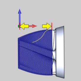
The Rotary Axis must be defined for the part.To setthe direction of the rotary axis, in the RotaryAxis group, select X Axis.
Because the machining origin was moved away fromthe center of rotation, this difference must be defined using the BasePoint parameter.
The following image shows the distance that is usedto set the base point.This is the distance from (1) the machining originto (2) the center of rotation of the part.
This parameter is an important part of proper toolpathcreation.

(You can click the ![]() MachineSetup item in the
MachineSetup item in the ![]() CAM Tree toview the machining origin.)
CAM Tree toview the machining origin.)
-
The only difference to report for this example is along theZ-axis.The radius of the part (and stock) is 3.2679 inches.
In the Base Point group, inthe Z box, type -3.2679. -
In the Cut Directiongroup, select Clockwise.
-
To finish the Patternsdialog box, click Next>>.
Part 9) The Parameters Dialog Box
-
In the Finishgroup, in the Stepover box,type 0.100.
-
To leave material for finishing, in the AllowanceXYZbox, type 0.050.
-
To calculate the toolpath, click Compute.

Notice that a single toolpath pass is created, forthe entire length of the part, that follows the selected surfaces.
The next step is to editthe feature and use the Along Rotary Axis options to limit the area ofthe part that is cut.
Part 10) Edit the Feature and Limit the Toolpath
-
When you computed the toolpath, the 4 AxisRotary feature was added to the CAM Tree.
To edit the feature, in the CAM Tree, right-click Feature4Axis Rotary, and click Edit.
 -
On the left side of the dialog box, clickParameters.
-
In the AlongRotary Axis group, select the
 Endcheck box, and type 4.00.
The toolpath now ends 4 inches from the MachineSetup instead of cutting the entire part.
(You can also limit the toolpath by changing theStart parameter to define where the toolpath starts in relation to theMachine Setup, along the defined Rotary Axis Direction.)
Tip: You canuse the Along Rotary Axis parameters Start and End, to define where thetoolpath starts and ends.(By default, the Rotary feature creates thetoolpath by cutting in the positive direction along the selected rotaryaxis.For example, with a A-axis rotary (rotation around the X-axis) thetoolpath is from left to right.)
-
To add the changes and view the results, click Compute.

Part 11) Create Multiple Passes
-
The next step is to add multiple passes tothe feature.
Edit the feature, and on the left side of the dialog box, click Parameters. -
In the MultiplePasses group, select the
MultiplePasses check box to enable the Roughing Passes and FinishingPasses groups. -
In the RoughingPasses group, in the Numberbox, type 2.
In the Spacing box, type 0.250. -
Next to SortBy, click the arrow and select Passes.
This causes the feature to cut each pass before moving on to the nextpass.In other words, this cuts the entire part to one depth beforemoving on to the next depth. -
To view the results, click Compute.
The toolpath now contains two passes instead ofthe single pass created earlier.
Notice that the multiple passes are created fromthe selected surface and are layered outward.(They are not layered fromthe stock inward.)


Part 12) Change the Cut Interval
Before simulating the program, there is one last change to make.Youcan see in the previous step that the tool is plunging, at rapid rate,into one of the deepest areas of the part geometry.The next steps causethe tool to plunge into a much more shallow area of the part.
-
Edit the feature, and click Patterns.
-
In the AngularStart/End group, select the CutInterval option.
-
In the AngleStart box, type -135.
-
In the AngleEnd box, type 225.
-
To add the changes and view the result, clickCompute.
The result is shown next.


Part 13) Simulate the Program
-
To view the part being cut, in the BobCAM menu, click
 Simulation.
To learn more about using simulation, view the Getting Started withSimulation.
-
For this example, it is important to understandthe Work Offset parameter that was previously defined in the MachineSetup.
To open the Machine Setup dialog box, in the CAM Tree, right-click Machine Setup,and click Edit. -
In the Machine Setup tab, under Work Offset,notice the XYZ values.
These XYZ values represent the distance from the machine zero to thepart zero (machining origin) defined in the Machine Setup.For thisexample, this is from the center of the face of the rotary table (machinezero) to the machining origin that is on the top of the cylindricalstock. -
Again, when the machining origin is not thesame as the machine zero, you must define the difference between thesetwo coordinate systems using the Work Offset dialog box.This is necessaryto create the proper machine simulation and NC program.
This concludes the tutorial.