How to Create a 4 Axis Wrapping Feature
Introduction
To create 4-axis wrapping features, you use the Wrapping Group in theCAM Tree.In this tutorial you use the Wrapping Group to add a millingfeature that cuts text around a cylindrical part.The part is a 6-inchcylinder that is created by the stock (no part model is used).The featuregeometry for this example is text.This tutorial provides a complete start-to-finishexample of creating a Milling Job, stock, machine setup, CAM feature,program simulation, and finally posting the program to output the NC program(G-code).
Example File
If you are connected to the Internet, the part file for this example can be downloaded automatically by clicking the following link: 4 Axis Wrapping Example 1.sldprt
Once you download and saved the zip file, extract the files on your system in an easy place to remember.You can then open the file to use with this tutorial.All files for the tutorials in this help system available for download can be found by clicking on the following link: http://www.bobcad.com/helpfiles.
The example file only contains thegeometry for the example, so you create the job, stock, and define themachine setup before creating the feature to cut the feature.
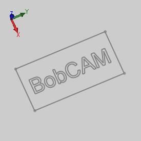
The sketch geometry for this example is shown next.The rectangle representsthe boundary of the cylindrical stock if it were unwrapped.
Tip:
Part 1) Create a Milling Job
-
In the PropertyManager, click the
 CAM Tree tab.
 -
Right-click
 CAMDefaults, and click NewJob.
 -
In the MachiningJob dialog box, select Milling.
-
Click to select the
 Start Stock Wizard check box.
 -
In the Machinegroup, click the arrow, and select BC_4x_Mill.
-
To start the job by defining the stock geometry,click
 (OK).
(OK).
Part 2) Create the Stock
-
In the Stock Specification,click
 Cylindrical.
 -
In the Stock Orientationgroup, click the Extrusion Directionarrow, and select X Axis.
-
In the Sizegroup, click Enter.Type thefollowing values:
-
 Diameter = 4.0
 -
 Height =6.0
 -
In the Stock Orientationgroup, click Enter Originand type the following values:
-
X =8.0
-
Y =4.0
-
Z =-2.0
-
Click
 Nextto go to the Machine Setup.
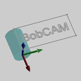
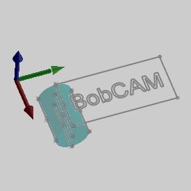
Notice the bounding entities that are automaticallycreated to aid in selected the machining origin for the part.
Part 3) Define the Machine Setup
-
In the MachineSetup tab, in the Origingroup, select Pick Origin,and click in the PickOrigin box.
-
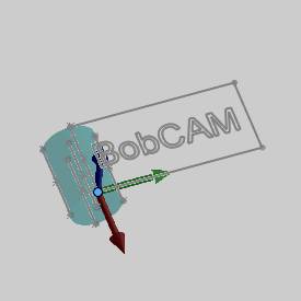
In the graphics area, click the end pointof the line on top of the stock as shown next.
This defines the machining origin location on the stock.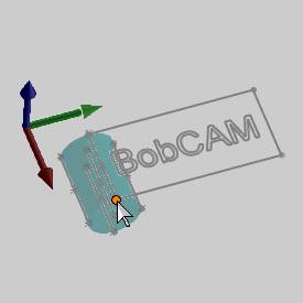
-
In the WorkOffset group, type the following values:
-
X= 0.0
-
Y =0.0
-
Z =2.0
This setting defines the distance from themachine zero to the machining (part) origin.In this example, becausethe machining origin is not the same as the machine zero, the differenceis reported in the Work Offset.This is required to create proper NC programsand simulation.(If the machining origin is placed at the center of rotation,then the work offset values are all 0.00.)
-
In the Othergroup, set the Clearance Planeto 0.625.
-
The Machine Setup is now defined.To finish the Machine Setup, click
 (OK).
(OK).
Part 4) Add the Wrapping Group to the Machine Setup
-
In the
 CAM Tree, right-click
 Machine Setup,point to Additional Functions,and click Add Wrapping Group.
 -
In the CAM Tree, right-click
 WrappingGroup, and click Edit.
The Wrapping Group dialog box displays. -
In the WrappingDiameter box, type 4.000.
-
Under WrappingAxis in the Origingroup, set the values to X0 Y0 Z-2.
This defines the distance from the machining origin (set at the topof the part) to the center of rotation. -
Make sure that the AxisDirection is set to X Axis.
The defines the direction of the rotary axis as parallel to the X-axis. -
In the ZeroDegree Location group, for Y= type 0.000.
This sets the distance, along the Y-axis, from the machining originto the zero degree location of the part.
To learn more about the zero degree location, view the breakdown atthe end of this tutorial. -
To accept the settings and close the dialogbox, click
 (OK).
(OK).
Part 5) Add a Milling Feature to the Wrapping Group and Select Geometry
-
In the CAM Tree, right-click
 WrappingGroup, and click Mill 2 Axis.
The 2 Axis Wizard displays. -
In the GeometrySelection dialog box, click SelectGeometry.
-
In the graphics area, select the text.
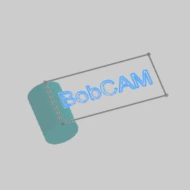
To accept the selection, click (OK).
(OK).
Click Next>>. -
In the Feature page, the Clearance Planeis automatically set using the value from the Machine Setup.
The default Rapid Plane (0.200) and Feed Plane (0.100) are both usedfor this example. -
Confirm that the Topof Feature is set to 0.000.
In the TotalDepth box, type 0.1250.
The settings defined in the Feature dialogbox are used for all operations in the feature.
Click Next>>to go to the Machining Strategy.
Part 6) Define the MachiningStrategy and Posting Parameters
-
In the Template group, select the Pocketingtemplate.
-
In the CurrentOperations group, select ProfileFinish, and click
 (Delete Operation).
The Current Operations group should now contain only one Pocket operation.
The Machining Strategy for the feature is now defined.
Click Next>> to go tothe Posting dialog box. -
The Work Offset # is automatically set usingthe offset selected in the Machine Setup.
-
Notice that the Output Rotary Angle checkbox is cleared.This parameter is used to create manual indexing programs,and it is not needed for this example.
-
In the ContourRamping Output group, you can select Line Moves or Arc Movesto define the output that your machine supports.
-
Click Next>>to go to the Multiaxis Postingdialog box.
Notice, at the top of the dialog box, that the UseMachine Settings check box is selected.
This means that the Multiaxis Posting parameters for the feature usethe same parameters as the machine that is selected in Current Settings.
You can clear the Use Machine Settingscheck box to define the Multiaxis Posting parameters of the featureseparately from the current machine settings. -
For this example, no changes are needed.
Click Next>>to go to the Tool page.
Part 7) Define the Tool Parameters
-
In the Diameterbox, type 0.125 and pressTab.
-
In the CornerRadius box, type 0.000and press Tab.
-
Using System Tool automatically updates thetool with tool parameters found in the Tool Library.
Notice that the holder is automatically assigned using the defaultholder stored with the tool. -
Click Next>>to go to the Patterns page.
Part 8) Define the Operation Parameters
-
In the Patternsgroup, confirm that Offset PocketOut is selected.
-
For this example the CutDirection is set to ClimbMill.
-
The Stepover% is set to 50.00.
-
Click Next>>to go to the Parameters page.
Part 9) Define the Remaining Parameters and Compute the Toolpath
-
For this example, set the SideAllowance to 0.000.
-
The Depthis set to Single Step forthe Total Depth of 0.125.
-
Click Next>>to go to the Leads page.
-
In the MaterialEntry group, select Plunge.
-
Click Next>> to go to the Machine Sequence page.
The Machine Sequence is used to optimize the order of machining whenselecting more than one chain for the feature.For this example thereare two options that can be used to produce the same result: Closestand X Direction.
In the Sort Order group, selectClosest.
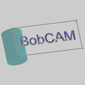
For this example, each letter is a separate pocket.The Closest parametercauses the feature to cut one pocket and then cut the next adjacent(closest) pocket instead of jumping back and forth between letters.This is done to create the most efficient cycle time for the feature. -
To create the toolpath, at the bottom ofthe dialog box, click Compute.
Part 10) Simulate the Part
-
To simulate the part, right-click
 MillingJob and click Simulation.
 -
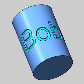
The part displays in the simulation window.For help with simulation, view Getting Started with Simulation.
Part 11) Post the NC Program
-
In the CAM Tree, right-click
 MillingJob, and click Post.
The NC program displays in the PostingManager tab.
Breakdown) About the Zero Degree Location
This section further examines the Zero DegreeLocation parameter of the Wrapping Group.This parameter is used to definewhat part of the toolpath is cut at the zero degree location of the cylinder.The Zero Degree Location parameter is the distance along the axis thatis perpendicular to the rotation axis of the part.This distance, measuredfrom the machining origin, defines what part of the feature is cut atthe zero degree location of the cylinder.(This value can be positiveor negative depending on how you set up the part and machining origin.)
The following explanation is given using thepart geometry as it is drawn (in a flat plane).Once you understand howthe parameter is applied in a flat plane, it is easier to understand howto apply the zero degree location as a distance around the cylinder.
-
The zero degree location of the cylindricalpart is shown next, marked by a cone at the end of the cylinder.
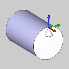
The second image shows the location of the machining origin on thepart (that was aligned with the zero degree location of the part).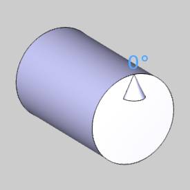
-
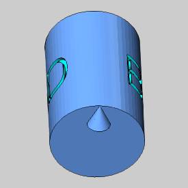
When you simulate the feature as createdin this example, you can see the zero degree location of the partdoes not contain any of the text.
-
The following image shows a dimension thatis added to measure the distance between the machining origin andthe start of the letter C in the BobCAM text.
(Notice that this distance is measured perpendicular to the rotationalaxis of the part.)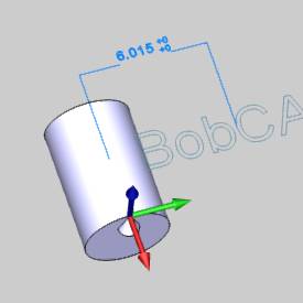
-
The next step is to set the Zero Degree Locationparameter, in the Wrapping Group dialog box, to the distance betweenthe machining origin and the beginning of the letter C. (Right-clickWrapping Group, and click Edit.)
The measured distance is used to set theZero Degree Location parameter.
When you compute the toolpath and simulatethe part, the start of the letter C is now aligned with the zero degreelocation of the cylinder as shown in the next image.
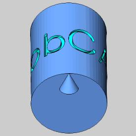
This example shows that you can use the ZeroDegree Location to change the location of the machining feature on thepart.
This concludes the tutorial.


