


How to Create a Multiaxis Cuts Along Curve Feature
Introduction
This tutorial explains how to create a Cuts Along Curve feature.Thisfeature requires the selection of a Lead Curve, which is used to createthe toolpath.The toolpath slices are created at a right angle to LeadCurve.This toolpath is applied to the second required selection, theDrive Surface.The Lead Curve can be on the surface, a surface edge, oryou can assign wireframe geometry as shown in this tutorial.If the LeadCurve creates intersecting toolpath segments, then the calculation willfail, and the curve must be recreated.
Example File
If you are connected to the Internet, the part file for this example can be downloaded automatically by clicking the following link: Cuts Along CurveExample 1.sldprt
Once you download and saved the zip file, extract the files on your system in an easy place to remember.You can then open the file to use with this tutorial.All files for the tutorials in this help system available for download can be found by clicking on the following link: http://www.bobcad.com/helpfiles.
In the example fileprovided, the stock and Machine Setup are already defined for the part.The part is simulated using the BC Table Table machine.
In this example, you create a toolpath that can be used to rough orfinish the outside of a cylinder.Instead of using a solid model, a surface(zero thickness) is used to show how the surface normal direction canbe changed to cut the opposite side of the surface.This action is thenapplied to this example to create a finishing toolpath for the insideof the cylinder.
Part 1) Add the Feature
-
In the PropertyManager, click the
 CAM Tree tab.
 -
Right-click
 MachineSetup and click Mill Multiaxis.
 -
In the MultiaxisWizard, click Surfaceand select Cuts Along Curve.
-
Click Next>>to go to the Posting dialogbox.
Part 2) Define the Posting Parameters
-
The Work Offset # is automatically set tothe value defined in the Machine Setup dialog box.
You can change the value here to update the Work Offset # for the feature. -
Click Next>>to go to the Multiaxis Postingdialog box.
Part 3) Define the Multiaxis Posting Parameters
-
Notice, at the top of the dialog box, that the Use Machine Settings checkbox is selected.
This means that the Multiaxis Posting parameters for the feature usethe same parameters as the machine that is selected in Current Settings.
You can clear the Use Machine Settingscheck box to define the Multiaxis Posting parameters of the featureseparately from the current machine settings.
An example usage is explained later. -
Click Next>>to go to the Tool page.
Part 4) Define the Tool Parameters
-
In the ToolData group, clear the
 System Tool check box.
Set the Diameter to 0.50and the Flute Length to 3.00.
Set the Corner Radius to 0.25 and the OverallLength to 5.00. -
Click AssignTool Holder.
In the Milling Tool Holder Library CAT 40 Holder list, click 0.5 inch I.D. Arbor CAT 40.
At the bottom of the dialog box, click OK.
(If you assign a tool holder to a tool in the Tool Library, that holderis automatically assigned and Step 2 can be eliminated.) -
Click Next>>to go to the Parameters dialogbox.
Part 5) Select Geometry
-
To define the lead curve, in the SurfacePaths tab under Pattern,click Lead.
-
In the graphics area,select the Lead Curve.
The toolpath for the feature is created normal (at a right angle) tothe curve.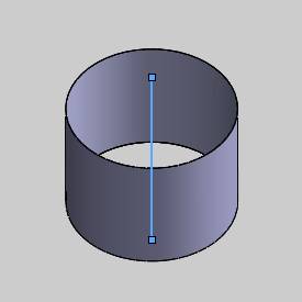
-
To confirm the selection, click
 (OK).
(OK). -
Click DriveSurfaces, and in the graphics area, select the geometry towhich the toolpath is applied.
-
To confirm the selection, click
(OK).
The geometry selection is complete.
Part 6) Define the Parameters and Compute the Toolpath
-
To leave stock material for a finish operation,in the Pattern group, in theDrive Surface Offset box,type 0.030.
-
In the Areagroup, next to Type, selectFull, Start and Endat Exact Curve EndPoints.
Notice by the name, that this parameter is in reference to the LeadCurve, and not the Drive Surface as is the case for the other surfacefeatures.Any part of the Lead Curve that can't be projected ontothe surface, is not used.So, for this example, this causes the firsttoolpath slice to start at the exact surface edge, or rather the exactcurve end points. -
In the Sortinggroup, next to Cutting Method,select Spiral.
-
In the Stepovergroup, set the Maximum Stepoverto 0.250 (A large stepoveris used to better show the toolpath).
-
At the top of the dialog box, click the Link tab.
At the bottom of the dialog box, click Retracts. -
In the ClearanceArea group, next to Type,select Cylinder, and set theRadius to 3.00.
Next to Direction, click thearrow and select Z Axis.
To close the dialog box, click OK. -
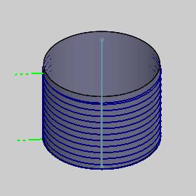
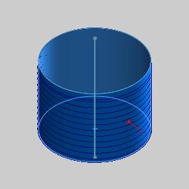
To view the toolpath as it is currently defined,at the bottom of the wizard, click Compute.
Notice the direction of the toolpath.Itis perpendicular to the Lead Curve.
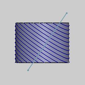
The following image shows the result witha Lead Curve that is diagonal to the cylinder.
Part 7) Curve Chain Direction
The chain direction of the selected curve is used to define the startand end of the toolpath.For example, this part is currently cutting fromthe bottom of the part to the top.
-
To view the chain direction of the curve,in the
CAMTree, right-click  Lead Curve and click Modify Start Point.(You may needto expand the
  Geometry folder of the Multiaxisfeature.)
 -
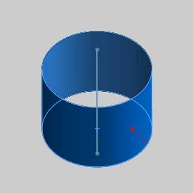
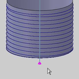
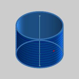
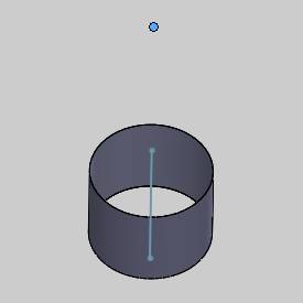
When you zoom-in to view the chain direction(the chain end-point is shown), you can see that it is starting atthe bottom and ending at the top of the cylinder.
-
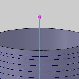
To change the chain direction, rotate thepart, and click the curve near the start point at the bottom of thecurve.
-
The chain direction of the curve is now fromthe top of the cylinder to the bottom.
-
To confirm the new direction, click
(OK).
(You can also, right-click Lead Curveand click Reverse Directionto flip the chain direction.) -
To add the changes to the feature: in theCAM Tree, right click
 FeatureMultiaxis, and click ComputeAll Toolpath.
The toolpath now starts at the top of thecylinder instead of the bottom.
Part 8) Simulation
For more help using simulation, view Getting Started with Simulation.
-
To view the program, in the BobCAMmenu, click
 Simulation.
 -
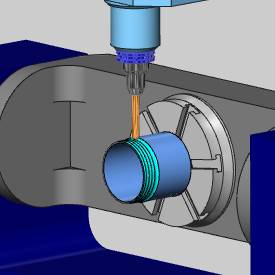
During simulation, you can see that the toolis cutting on the outside of the cylinder.
-
To close simulation, in the BobCAMmenu, click
 Exit Simulation.
Adjust the Machine Table Rotation
When you simulate the program, the machine table is sometimes rotated in a way that doesn't allow you to view the part without rotating the view of the machine. You can change the Angle Pair settings for the feature to modify the table rotation used in simulation and in the posted code.
- To edit the feature, in the CAM
Tree, right click FeatureMultiaxis,
and click Edit.
- Click the
Multiaxis Posting icon in the tree.
- Clear the Use
Machine Settings check box.
- In the Angle
Pair group, next to Use,
select Other Solution.
When you simulate the program again, you can now view the part being cut from the opposite side of the machine.
The table is rotated to use the other solution to the rotation angles of the primary and secondary rotary axes (angle pair). This changes the posted output of the program as well as the simulation.
Tip: You don't have to compute the toolpath to update this setting for simulation, but you must Post the program to update the code if has already been posted.
Part 9) About the Surface Normal
The surface normal of Drive Surfaces must point away from the DriveSurface in order to create the toolpath on the proper side of the surface.For this example, because the geometry used for the part is a surfaceand not a solid, the surface normal can be used to reverse the machiningside of the part.To elaborate, if the cylindrical shell/surface is givena thickness, meaning that there is an outer surface and an inner surface,then there is a normal for each surface.In this case, the outer surfacenormal must point out, and the inner surface normal must point in. Themachining is then applied to the selected surface.
-
To view the surface normal you must openthe Selection Manager.
Under the ![]() Geometryfolder of
Geometryfolder of ![]() FeatureMultiaxis, right-click
FeatureMultiaxis, right-click ![]() Drive Surfaces and click Re/Select.
Drive Surfaces and click Re/Select.
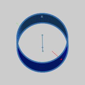
The surface normal direction displays forall surfaces/faces during geometry selection for Multiaxis features.
-
The next step is to reverse the surface normal to force thetool to cut the inside of the surface.
In the SelectedItems box, click Face <1>,and click Reverse Normal.
The surface normal now points to the insideof the cylinder.
-
To finish and close the Selection Manager, click
(OK). -
To add the changes to the feature, right-click
 Multiaxis,and click Compute Toolpath.
The toolpath is now applied to the insideof the surface.
If you were to simulate the part now, itshows that the tool is plunging directly though the part.
This is a result of the default tool axisorientation, which uses the surface normal to align the tool.This meansthat the tool orientation is at a right angle to the surface at any point(perpendicular to the tangent at the contact point.)
The tool axis orientation must be changedto correct the feature.
Part 10) Tool Axis Orientation
-
In the CAMTree, right-click
FeatureMultiaxis,and click Edit. -
Click Parameters,and click the Tool Axis Controltab.
-
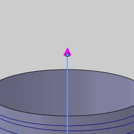
Next to ToolAxis Will, select the tilting strategy TiltedThrough Point.
-
Below TiltedThrough Point, click TiltPoint.
You can type coordinate values to definethe point, or for this example, click the point that is above the cylinder.
Notice that the XYZ values are updated fromthe selected point.
To confirm the settings and close the dialogbox, click ![]() (OK).
(OK).
Part 11) Clearance Area
Now that the inside of the cylinder is being machined, the ClearanceArea is changed to a plane above the part.
-
Click the Linktab, and at the bottom of the dialog box, click Retracts.
-
In the ClearanceArea group, next to Type,select Plane.
In the Height box, type 5.000.
To close the dialog box, click OK. -
To add the changes to the feature, clickCompute.
Notice that the toolpath moved further away from the surface (thisis a result of changing the tool orientation which changed the toolcontact point on the surface).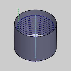
-
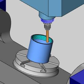
To view the program, in the BobCAMmenu, click
Simulation.
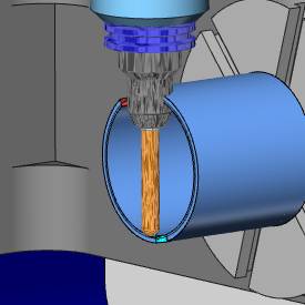
The toolpath is now a finishing operationfor the inside of the cylinder.
The tool axis orientation is always tiltedthrough the selected point.
This concludes the tutorial.