


How to Create a Multiaxis Parallel Cuts Feature
Introduction
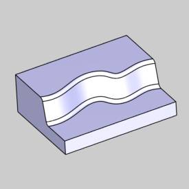
This tutorial explains how to create a Multiaxis Surface Parallel Cutsfeature.The Parallel Cuts feature is used to create parallel cuts alonga selected surface geometry.Only a Drive Surface selection is requiredfor the feature, which can be one or more surfaces.
Example File
If you are connected to the Internet, the part file for this example can be downloaded automatically by clicking the following link: Parallel CutsExample 1.sldprt
Once you download and saved the zip file, extract the files on your system in an easy place to remember.You can then open the file to use with this tutorial.All files for the tutorials in this help system available for download can be found by clicking on the following link: http://www.bobcad.com/helpfiles.
In the example fileprovided, the stock and Machine Setup are already defined for the part.The part is simulated using the BC Table Table machine.
In this example, a finishing toolpath strategy is applied to the curvedface of the part model.You learn how the surface normal direction definesthe tool orientation and how to apply a tilting strategy to change thisorientation and resolve a gouge.You also examine how changing the Linkparameters modifies the toolpath and tool/machine movement.The last partexplains applying a gouge check to the model.
Part 1) Add the Feature
-
In the PropertyManager, click the

-
Right-click
 MachineSetup and click Mill Multiaxis.
 -
In the MultiaxisWizard, click Surface,and confirm that Parallel Cutsis selected.
-
Click Next>>to go to the Posting dialogbox.
Part 2) Define the Posting Parameters
-
The Work Offset # is automatically set tothe value defined in the Machine Setup dialog box.
You can change the value here to update the Work Offset # for the feature. -
Click Next>>to go to the Multiaxis Postingdialog box.
Part 3) Define the Multiaxis Posting Parameters
-
Notice, at the top of the dialog box, that the Use Machine Settings checkbox is selected.
This means that the Multiaxis Posting parameters for the feature usethe same parameters as the machine that is selected in Current Settings.
You can clear the Use Machine Settingscheck box to define the Multiaxis Posting parameters of the featureseparately from the current machine settings.
An example usage is explained later. -
Click Next>>to go to the Tool page.
Part 4) Define the Tool Parameters
-
In the ToolData group, set the Diameterto 0.50, and the CornerRadius to 0.25.
-
Click AssignTool Holder.
In the Milling Tool Holder Library CAT 40 Holder list, click 0.5 inch I.D. Arbor CAT 40.
At the bottom of the dialog box, click OK.
(If you assign a tool holder to a tool in the Tool Library, that holderis automatically assigned and Step 2 can be eliminated.) -
Click Next>>to go to the Parameters dialogbox.
Part 5) Select Geometry
-
To enable selection mode, in the Patterngroup of the Surface Pathstab, click Drive Surfaces.
In the graphics area, select the surface geometry to which the toolpathis applied (as shown next).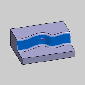
-
To confirm the selection, click
 (OK).
(OK). -
You are now ready to define the parametersfor the feature.
Before doing so, at the bottom of the dialog box, click Finish. -
Notice that the
 Multiaxisfeature is added to theCAM Tree.
You can use the feature in the CAM Tree to edit many of the geometryselection that are made from the Multiaxis Wizard dialog box. -
To return to the Multiaxis Wizard and editthe feature, right-click
Feature Multiaxis,and click Edit. -
On the left side of the dialog box, clickParameters.
Part 6) Feature Setup
-
In the Patterngroup, click Constant Z.
Notice that this sets the Machine Angle in Z parameter to 0 and disablesthe Machine Angle in XY parameter.
This is used to create toolpath cuts that have a constant Z-axis value. -
In the Sortinggroup, set the Cutting Methodto One Way.
-
In the Stepovergroup, set the Maximum Stepoverto 0.050.
-
At the top of the dialog box, click Link.
Near the bottom of the dialog box, click Retracts.
Confirm that the Directionis set to ZAxisand the Height is set to 4.75.
This value is automatically set from the value define in the MachineSetup (but only when the feature is created).
You can change the value here to update the Clearance Plane after creatingthe feature.
Click OK. -
To view the result, at the bottom of thedialog box, click Compute.
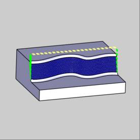
Notice that the toolpath Links are retracting to the Clearance Areabetween each slice.
You can also see that no lead-in or lead-out is defined. -
To edit the feature, right-click
FeatureMultiaxis, and click Edit.
Part 7) Edit the Links
-
On the left side of the dialog box, clickParameters.
At the top of the dialog box, click the Linktab. -
In the Entry/Exitgroup, for First Entry, (onthe right side) select Use Lead-In.
To open the Lead-In dialogbox, click .
.
Confirm that the Use Default Lead-Incheck box is selected, and click OK. -
Next to LastExit, (on the right-side) select UseLead-Out.
-
To open the DefaultLead-In/Out dialog box, at the bottom of the dialog box, clickDefault Lead-In/Out.
In the Lead-In group, nextto Type, select TangentialLine.
At the top of the dialog box, next to Copy,click .
.
This copies the selected Lead-In parameters to the Lead-Out group.
To accept the changes and close the dialog box, click OK. -
In the LinkBetween Slices group, set the LargeMoves to Retract to RapidDistance.
(To view the current distance values in the Retracts dialog box, clickRetracts.) -
To view the changes, click Compute.
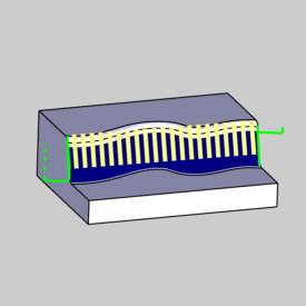
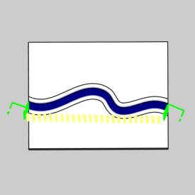
The result shows that the First Entry and Last Exit moves now use aLead-In and a Lead-Out.Also, instead of the tool retracting to the ClearancePlane at the end of each slice, it now retracts to the Rapid Plane.(Theserapid moves are shown in yellow.) You can compare these results to thetoolpath result shown earlier.Notice that the yellow rapid moves arein front of the selected drive surface and not above it as it was earlier.This is the difference between Retract to Clearance Area and Retract toRapid Distance.
Part 8) Simulation
-
To view the part being cut, in the BobCAM menu, click
 Simulation.
To learn more about using simulation, view Getting Started with Simulation. -
When you simulate the program, you see thatthe tool orientation is always the same as the surface normal directionalong the surface.
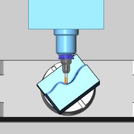
During simulation, you can also see thatthe part is gouged because of the short tool length.The gouge happensat the end of the toolpath, because there is not enough clearance betweenthe lower surface and the tool holder.
This issue could be resolved by using a longertool, but maybe you don't have a longer tool to use for the job.
Part 9 and Part 11 explain ways to resolvesuch a problem.
-
To close simulation, in the BobCAMmenu, click
 Exit Simulation.
Adjust the Machine Table Rotation
When you simulate the program, the machine table is sometimes rotated in a way that doesn't allow you to view the part without rotating the view of the machine. You can change the Angle Pair settings for the feature to modify the table rotation used in simulation and in the posted code.
- To edit the feature, in the CAM
Tree, right click FeatureMultiaxis,
and click Edit.
- Click the
Multiaxis Posting icon in the tree.
- Clear the Use
Machine Settings check box.
- In the Angle
Pair group, next to Use,
select Other Solution.
When you simulate the program again, you can now view the part being cut from the opposite side of the machine.
The table is rotated to use the other solution to the rotation angles of the primary and secondary rotary axes (angle pair). This changes the posted output of the program as well as the simulation.
Tip: You don't have to compute the toolpath to update this setting for simulation, but you must Post the program to update the code if has already been posted.
Part 9) Using Tool Axis Control
In this part of the tutorial, you use the Tool Axis Control tab to tiltthe tool orientation away from the bottom surface.
-
Edit the feature, click Parameters,and click the Tool Axis Controltab.
-
Next to ToolAxis Will, the Tilting Strategy is set to TiltedRelative to Cutting Direction.
This tilting strategy uses the surface normal direction to define thetool orientation.In addition to this tool orientation, you can definea lead angle (forward or backward) and a side angle (left or right)based on the direction that the tool is moving. -
To tilt the tool to the right of the toolpathbased on the cut direction, in the TiltAngle at Side of Cutting Direction, type 45.00.
-
To add the changes to the program, clickCompute.
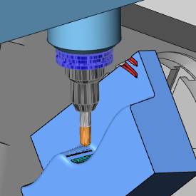
The tool tilting is visible in the toolpath display.
This has caused the rapid movements (links) to move up away from thebottom surface. -
To simulate the program, on the BobCAMtoolbar, click
Simulation.
During simulation, you can observe that the tool orientation is nowtilted 45 degrees to the right of the toolpath (in the cutting direction).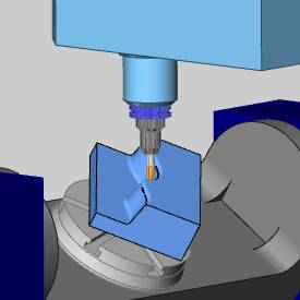
-
Because of the new tool orientation, thetool holder no longer gouges the part.
To close simulation, on the BobCAMtoolbar, clickExit Simulation.
Part 10) About Flip Step Over
When using the Tilt Angle at Side of Cutting Direction parameter, itis important to understand the result created when using Flip Step Over.
-
Edit the feature, and click Parameters.
-
In the SurfacePaths tab, in the Sortinggroup, select the Flip Step Overcheck box.
-
Change the CuttingMethod to ZigZag.
-
To view the results, click Compute.
Because of the two previous settings, the toolpath now starts at thebottom-left corner of the surface and ends at the top-right corner.
Also, the toolpath now alternates the cutting direction for each slicewhich eliminates the retract and rapid moves.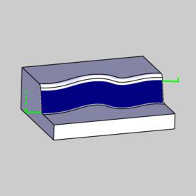
-
Simulate the part to view the result.
Simulation shows that the tool orientationis still tilted 45 degrees in the same direction as it was previously,even though the toolpath is now cutting in both directions.(See the followingtip about tool orientation.)
This is the desired result for this example.
Important: To causethe tool side tilt angle to change orientation with each alternating slice,you must enable Allow Flipping Side Direction.To enable this parameter,in the Tool Axis Control tab,next to Side Tilt Definition,click Advanced.In the Advanceddialog box, select the ![]() Allow Flipping Side Directioncheck box.
Allow Flipping Side Directioncheck box.
Part 11) Using Gouge Check
The Gouge Check tab is used next to check the program and correct anyfurther gouges.
-
Edit the feature and navigate to the Gouge Check tab.
-
To turn on a gouge check: in the Statusgroup, above 1, select the
 check box.
In the Check group, selectthe four check boxes for the Flute, Shaft, Arbor, and Holder. -
In the Strategyand Parameters group, in the first box, select TiltTool.
In the next box, select Use Side TiltAngle. -
To check the values used, click Parameters.
Confirm that the Parametersdialog box shows a Max.Tilt Angleof 90 degrees and a Min.Tilt Angle of -90.
Important: The MaximumTilt Angle can be between 0 and 180 degrees and this determines the amountof tilting to the left of the cutting direction when using Use Side TiltAngle.(When using Use Lead/Lag Tilt Angle this determines the amountof tool tilting forward or towards the cutting direction.) The MinimumTilt Angle determines the amount of tilting to the right of the cuttingdirection and can be between -180 and 0 degrees.(When using Use Lead/LagAngle, this determines the amount of tilting backwards from the cuttingdirection.)
Set the ClearanceAngle to 3 degrees.
To close the dialog box, click OK.
-
In the Geometry group, the
Drive Surfaces and CheckSurfaces check boxes are selected.
To select the CheckSurfaces, or the surfaces that are gouge checked, click ![]() .
.
In the graphics area, select the surfacesto include in the gouge check.
For this example, select the entire part,and then click the Drive Surface to remove it from the selection.
The resulting selection should appear asfollows.
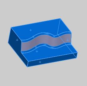
To confirm the selections, click ![]() (OK).
(OK).
-
To calculate the toolpath with the gouge check, click Compute.
Adding the gouge check in this example removesany remaining gouges.
You can compare the results of using theside-tilt angle or creating a gouge check by using only one or the otherto calculate the toolpath and then simulating each result.
Tip: Whengouge checking a feature, you should always try to get the feature asclose as possible to the desired result before you add the gouge check.This way you are only using the gouge check to make small changes to thetoolpath.The point here is that you should not rely on the gouge checkto fix a poorly created feature.
This concludes the tutorial.