


How to Create a Multiaxis Parallel to Surface Feature
Introduction
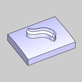
This tutorial explains how to create a Parallel to Surface feature.The feature uses a leading surface that is adjacent to the drive surfaceand creates a toolpath of parallel offsets from the leading surface, onthe selected drive surface.
Example File
If you are connected to the Internet, the part file for this example can be downloaded automatically by clicking the following link: Parallel toSurface Example 1.sldprt
Once you download and saved the zip file, extract the files on your system in an easy place to remember.You can then open the file to use with this tutorial.All files for the tutorials in this help system available for download can be found by clicking on the following link: http://www.bobcad.com/helpfiles.
In the examplefile provided, the stock and Machine Setup are already defined for thepart.The part is simulated using the BC Table-Table machine.
In this example, you learn how to create a toolpath of parallel cutson a surface using an adjacent surface edge to define the path.A side-tiltangle is applied to show you how to change the default tool orientation.You also learn how to create a margin to offset the tool from the adjacentsurface.How to add a gouge check is also explained.
Part 1) Add the Feature
-
In the PropertyManager, click the CAM Tree tab.
-
Right-click
 MachineSetup and click Mill Multiaxis.
 -
In the MultiaxisWizard, select Surfaceand click Parallel to Surface.
-
Click Next>>to go to the Posting dialogbox.
Part 2) Define the Posting Parameters
-
The Work Offset # is automatically set tothe value defined in the Machine Setup dialog box.
You can change the value here to update the Work Offset # for the feature. -
Click Next>>to go to the Multiaxis Postingdialog box.
Part 3) Define the Multiaxis Posting Parameters
-
Notice, at the top of the dialog box, that the Use Machine Settings checkbox is selected.
This means that the Multiaxis Posting parameters for the feature usethe same parameters as the machine that is selected in Current Settings.
You can clear the Use Machine Settingscheck box to define the Multiaxis Posting parameters of the featureseparately from the current machine settings.
For this example, no changes are needed. -
Click Next>>to go to the Tool page.
Part 4) Define the Tool Parameters
-
Clear the
 SystemTool check box.
Set the Diameter to 0.50and the Flute Length to 3.00.
Set the Corner Radius to 0.25 and the OverallLength to 5.00. -
Click Next>>to go to the Parameters dialogbox.
Part 5) Select Geometry
-
To define the lead surface, in the Surface Paths tab, in the Pattern group, click SingleEdge.
-
In the graphics area,select the two surfaces as shown next.


-
To accept the selections, click
 OK.
OK. -
To define the surface being machined, inthe Multiaxis Wizard, clickDrive Surfaces.
In the graphics area, select the drive surface as shown next.
-
To accept the selections, click
OK.
The geometry selections for the feature are complete.
Part 6) Define the Parameters
-
In the Areagroup, next to Type, selectDetermined by Number of Cuts.
In the Number of Cuts box,type 6.00. -
In the Sortinggroup, next to Cutting Method,select One Way.
Next to Direction for One Way Machining,select Climb. -
In the Stepovergroup, next to Maximum Stepover,type 0.100.
-
At the top of the dialog box, click Link.
Near the bottom of the dialog box, clickRetracts.
In the ClearanceArea group, confirm that the Typeis set to Plane, with the Direction set to ZAxis.
Confirm that the Heightis set to 5.000.
This value is automatically set based onthe Clearance Plane value from the Machine Setup dialog box.The valuefrom the Machine Setup is only automatically set for the feature whenyou create the feature.Once the feature is created, you can edit theclearance plane value for the feature in this location (changing the valuein the Machine Setup does not update existing Multiaxis features).
Click OKto close the Clearance Area dialog box.
-
To create a toolpath with the current settings, at the bottomof the dialog box, click Compute.


Notice the toolpath at the edge of the island.You can see that this will cut into the island in the middle of the partbecause the first toolpath pass is at the exact edge where the two surfacesmeet.
A Margin must be defined.
Part 7) Edit the Feature and Define a Margin
-
When you computed the toolpath, the
 Multiaxis feature was added to theCAM Tree.
To edit the feature, right-clickFeatureMultiaxis, and click Edit.
The Multiaxis Wizard displays. -
On the left side of the dialog box, clickParameters.
-
In the Areagroup, next to Type, clickMargins.
The Margins dialog box displays. -
In the StartMargins box, type the radius of the tool which is 0.250.
(For this example, you could select the Add Internal Tool Radius checkbox instead of typing the value in the Start Margins box.Either methodprovides the same result.) -
To accept the changes and close the dialogbox, click OK.
-
To add the change to the feature, click Compute.
The margin between the surfaces is appliedas shown next.


Part 8) Simulation
-
The next step is to simulate the programto look for any necessary changes.
In the BobCAM menu, click Simulation.
For help with simulation, view Getting Started with Simulation. -
During Simulation, it is shown that the toolaxis is always normal to the selected drive surface.
The next step is to add a side tilt angle.


When the simulation is finished, click ![]() Exit Simulation.
Exit Simulation.
Part 9) Define the Side Tilt Angle
-
Right-click
FeatureMultiaxis, and click Edit. -
On the left side of the MultiaxisWizard, click Parameters.
-
At the top of the dialog box, click Tool Axis Control.
-
Next to ToolAxis Will, confirm that TiltedRelative to Cutting Direction is selected.
-
Next to TiltAngle at Side of Cutting Direction, type a value of 20.00.
-
To add the change to the feature, at thebottom of the Multiaxis Wizard,click Compute.


-
You can see that the side tilt angle hasbeen applied by observing the direction of the plunge (exit and entry)moves (shown in green in the previous image).
To view the result, simulate the program.
You can see that a 20 degree side tilt angleis added to the tool axis orientation.

Part 10) Create a Gouge Check
-
For the last step of this tutorial, a gougecheck is added to the feature.
Edit the feature. -
In the MultiaxisWizard, click Parameters.
At the top of the dialog box, click GougeCheck. -
On the left side, in the Statuscolumn, select the
 check box above 1.
In the Check column, selectthe check box for the Flute and the Shaft.
In the Strategy and Parameterscolumn, select TiltTool.
Below Tilt Tool, select Use Side Tilt Angle. -
To define the check surfaces, in the Geometry column, with both checkboxes selected, click
 .
.
In the graphics area select all of the island surfaces in the middleof the part, as shown next.
To accept the selections, clickOK. -
To add the gouge check to the feature, clickCompute.
If any gouges are found, an additional tiltangle is applied to the tool orientation until the feature is no longergouging.
In this example, no further gouges are found.
This concludes the tutorial.