How to Create a Multiaxis Project Curves Feature
Introduction
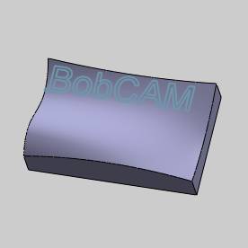
This tutorial explains how to create a Project Curves Multiaxis feature.The feature projects a user defined geometry curve onto the drive surfacein order to create the toolpath.The curve that is projected onto thedrive surface can be geometry that is selected, or it can be a patternthat is defined in the Surface Paths tab of the Multiaxis Wizard.Thistutorial explains using geometry from the graphics area.
Example File
If you are connected to the Internet, the part file for this example can be downloaded automatically by clicking the following link: Project Curves Example 1.sldprt
Once you download and saved the zip file, extract the files on your system in an easy place to remember.You can then open the file to use with this tutorial.All files for the tutorials in this help system available for download can be found by clicking on the following link: http://www.bobcad.com/helpfiles.
In the example fileprovided, the stock and Machine Setup are already defined for the part.The part is simulated using the BC Table-Table machine.
Part 1) Add the Feature
-
In the PropertyManager, click the CAM Tree tab.
-
Right-click
 MachineSetup and click Mill Multiaxis.
 -
In the MultiaxisWizard, select Surfaceand click Project Curves.
-
Click Next>>to go to the Posting dialogbox.
Part 2) Define the Posting Parameters
-
The Work Offset # is automatically set tothe value defined in the Machine Setup dialog box.
You can change the value here to update the Work Offset # for the feature. -
Click Next>>to go to the Multiaxis Postingdialog box.
Part 3) Define the Multiaxis Posting Parameters
-
Notice, at the top of the dialog box, that the Use Machine Settings checkbox is selected.
This means that the Multiaxis Posting parameters for the feature usethe same parameters as the machine that is selected in Current Settings.
You can clear the Use Machine Settingscheck box to define the Multiaxis Posting parameters of the featureseparately from the current machine settings.
For this example, no changes are needed. -
Click Next>>to go to the Tool page.
Part 4) Define the Tool Parameters
-
To define the tool, click ToolCrib.
In the Tool Crib, on the leftside, click the Endmill Roughcategory.
At the bottom of the dialog box, click AddFrom Tool Library. -
In the SelectTool dialog box, click anywhere in the row labeled 1/32Flat Endmill - Standard (you may need to drag the bar, at thebottom of the window, to the right to view the full label).
The row of the selected tool changes color to show that it is selected.
To confirm the selection, at the bottom of the SelectTool dialog box, click OK.
To add the tool to the feature, atthe bottom of theMillingTool Crib, clickOK. -
Depending on your Tool Library, a tool holdermay already be assigned for the selected tool.A holder is assignedif the Holder Label box displays a label (and the Assign Tool Holderbutton is labeled Remove Tool Holder).If a holder is already assigned,skip to step 4.
To assign a tool holder, click AssignTool Holder.
In the Milling Tool Holder Library,in the CAT 40 Holder list,click anywhere in the row labeled 0.25inch I.D. Arbor CAT 40.
The row of the holder changes color to show that it is selected.
At the bottom of the Milling ToolHolder Library, click OK. -
Click Next>>to go to the Parameters dialogbox.
Part 5) Select Geometry
-
In the SurfacePaths tab, in the Patterngroup next to Type, selectUser Defined.
To define the projection curves, click Projection. -
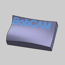
In the graphics area, select the projectioncurves (text).
-
To accept the geometry selection, click
 OK.
OK. -
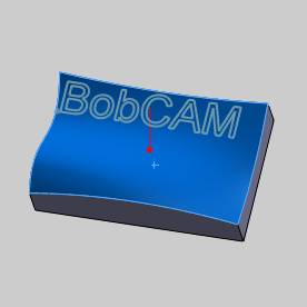
To define the surface being machined, inthe Pattern group, click Drive Surfaces.
-
In the graphics area, click to select thedrive surface as shown next.
-
To accept the geometry selection, click
 OK.
OK.
The geometry selection for the feature iscomplete.
Part 6) Define the Parameters
-
In the Patterngroup, next to Projection Direction,select Z-axis.
This projects the selected geometry along the Z-axis. -
In the DriveSurfaces Offset box, type -0.01.
This forces the tool into the stock (in-feed) by the specified value. -
At the top of the dialog box, click Link.
-
At the bottom of the dialog box, click Retracts.
In the ClearanceArea group, confirm that the Heightis set to 2.00.
This value is automatically set tothe value that was previously set in the Machine Setup dialog box whenthe feature is created.(Updating the Clearance Plane in the Machine Setupdoesn't update existing Multiaxis features.)
To close the Retracts dialog box, click OK.
-
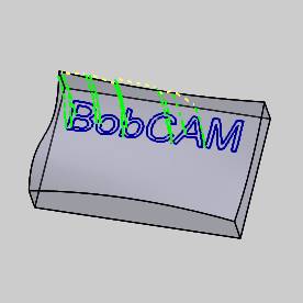
To calculate the toolpath, at the bottom of the MultiaxisWizard, click Compute.
The result is shown next.The ProjectionCurves text is hidden, and the part is made transparent to better showthe toolpath.
(Because of the negative drive surface offsetvalue, the toolpath is below the surface of the part geometry.)
Part 7) Simulate the Program
-
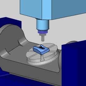
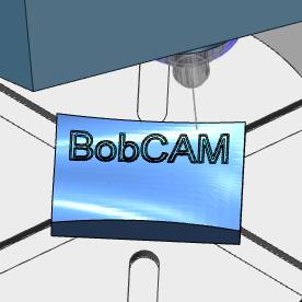
To view program simulation, in the BobCAM menu, click
 Simulation.
For help with simulation, view Getting Startedwith Simulation.
-
To close the simulation, in the BobCAMmenu, click
 Exit Simulation.
This concludes the tutorial.


