


How to Create a Multiaxis Swarf Feature
Introduction
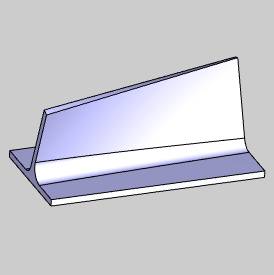
This tutorial explains how to create a Multiaxis Swarf feature.Thegoal of swarf milling is to create the desired cut using the entire flutelength of the tool.This is great for machining fluid parts such as blisks(bladed disks) and impellers.
Example File
If you are connected to the Internet, the part file for this example can be downloaded automatically by clicking the following link: Swarf Example 1.sldprt
Once you download and saved the zip file, extract the files on your system in an easy place to remember.You can then open the file to use with this tutorial.All files for the tutorials in this help system available for download can be found by clicking on the following link: http://www.bobcad.com/helpfiles.
In the example file provided,the stock and Machine Setup are already defined for the part.The partis simulated using the BC Table Table machine.
This example uses the Automatic strategy and what is explained herecan be applied to the other Swarfing strategies.Adding leads, creatingmultiple steps, adding a gouge check, and an important note on machinemovement are also explained.
Part 1) Add the Feature
-
In the PropertyManager, click the
 CAM Tree tab.
 -
Right-click
 MachineSetup and click Mill Multiaxis.
 -
In the MultiaxisWizard, select Swarf Machining.
-
Click Next>>to go to the Posting dialogbox.
Part 2) Define the Posting Parameters
-
The Work Offset # is automatically set tothe value defined in the Machine Setup dialog box.
You can change the value here to update the Work Offset # for the feature. -
Click Next>>to go to the Multiaxis Postingdialog box.
Part 3) Define the Multiaxis Posting Parameters
-
Notice, at the top of the dialog box, that the Use Machine Settings checkbox is selected.
This means that the Multiaxis Posting parametersfor the feature use the same parameters as the machine that is selectedin Current Settings.
You can clear the UseMachine Settings check box to define the Multiaxis Posting parametersof the feature separately from the current machine settings.
For this example, no changes are needed.
-
Click Next>> togo to the Tool page.
Part 4) Define the Tool Parameters
-
In the ToolData group, set the Diameterto 0.75 and set the Corner Radius to 0.00.
Clear the SystemTool check box, and set theFlute Length to 2.00.
 -
Click AssignTool Holder.(If the Holder Label box displays the tool holdername, skip this step.)
In the Milling Tool Holder Library CAT 40Holder list, click 0.75 inch I.D. ArborCAT 40.
At the bottom of the dialog box, click OK.
(If you assign a tool holder to a tool inthe Tool Library, that holder is automatically assigned and Step 2 canbe eliminated.)
-
Click Next>> togo to the Parameters dialogbox.
Part 5) Select Geometry
-
For this example, we are using the Automaticstrategy because it always uses a Swarf Surface selection.(We useall of the Automatic options for Swarf and only change what is neededto get the desired result.)
-
Next to SwarfSurfaces, click
 .
.
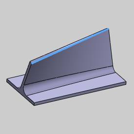
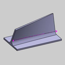
In the graphics area, select the swarf surfaceas shown next.
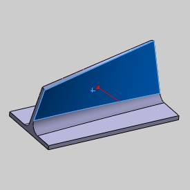
To confirm the selection, click ![]() OK.
OK.
-
The geometry selection for this example is now complete.
Note: The geometry selections for swarf machiningchange depending on the Strategy selected.With any strategy, you havethe option to select the Upper and Lower Curves which are used to alignthe tool.The curves are split into equal-length segments and the matchingpoints for each segment are used to create the tool orientation.Selectingthe Upper and Lower Curves gives you control of the cutting side and directionfor the feature.If you don't select the curves when using the Automaticstrategy, the system attempts to find the correct curves and cutting directionautomatically using only the selected swarf surfaces.
Part 6) Define the Parameters and Create the Toolpath
-
To leave material for finishing, in the Swarf Offset box, type 0.30.
-
At the top of the dialog box, click Link.
-
Near the bottom of the dialog box, clickRetracts.
In the Clearance Area group, confirm thatthe Type is set to Plane,and the Direction is ZAxis.
Confirm that the Heightis set to 4.000.
This value is automatically set (but onlywhen the feature is created) using the Clearance Plane value from theMachine Setup.
You can modify the Clearance Plane for thefeature in this location at any time.
Click OKto close the Retracts dialog box.
-
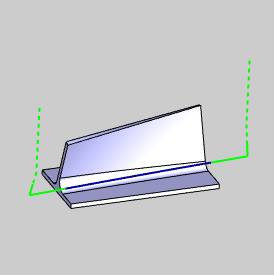
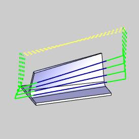
To view the feature as it is currently defined, at the bottomof the dialog box, click Compute.
The result is shown next.
-
Notice that the toolpath computed on the wrong side of the part.
This is resolved in the next part of thistutorial.
For you, the toolpath may have calculatedon the proper side of the part.If it did, then you do not have to changethe Machining Side as explained in the next part.
Part 7) Edit the Feature
-
To edit the feature, in the CAMTree, right-click
 Feature Multiaxisand click Edit.
 -
On the left side of the MultiaxisWizard dialog box, click Parameters.
In the Machining group, nextto Side, click the arrow andselect Left. -
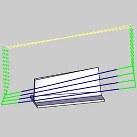
At the bottom of the dialog box, click Compute.
The toolpath is now on the proper side ofthe part.
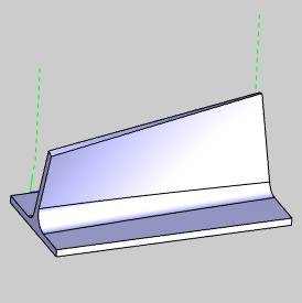
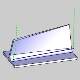
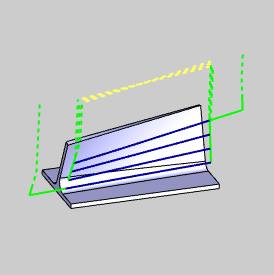
Tip: The Automatic options for Swarf machining work well for most parts.In the event that you have trouble creating the proper toolpath, you maywant to turn on the Upper Curve and Lower Curve geometry items and assignthe edges of the Swarf surface as shown next.
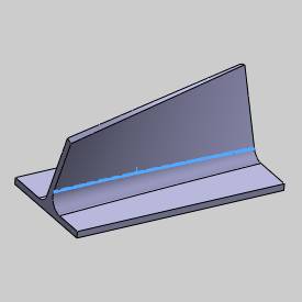
After selecting the Upper Curve and Lower Curve, you can then set theMachining Direction to Follow Lower Curve Chaining and set the directionof the lower curve as explained next.
-
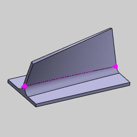
To view the StartPoint, in the CAM Tree,right-click
 LowerEdge Curve and click ModifyStart Point.(You may need to expand the Geometry folder ofthe Multiaxis feature.)
 -
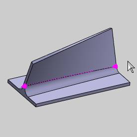
In the graphics area, the start point becomes visible.
To change the start point (direction), clicknear the end of the entity, and then click ![]() OK.
OK.
-
In addition to the previous method, to reverse the direction,you can right-click
Lower EdgeCurve, and click Reverse Direction.
Part 8) Add Leads
Notice that the toolpath is plunging directly into the edge of the partgeometry.This is not the desired result for this example.(To simulatethe feature and review the result, in the BobCAM menu, click Simulation.)Next, you add a lead-in and a lead-out to cause the tool to plunge outsideof the part, so that the side of the tool is used to begin the cut.
-
In the
CAMTree, right-click Feature Multiaxis,and click Edit.
On the left side of the dialog box, click Parameters.
At the top of the dialog box, click the Linktab. -
In the Entry/Exitgroup, next to First Entry,(on the right side) select Use Lead-In.
Next to UseLead-In, click ![]() to open the Lead-in dialog box.
to open the Lead-in dialog box.
Notice at the top of the dialog box, thatthe ![]() Use DefaultLead-In check box is selected.
Use DefaultLead-In check box is selected.
To close the dialog box, click OK.
-
In the Entry/Exit group,next to Last Exit, (on theright side) select Use Lead-Out.
-
At the bottom of the dialog box, click DefaultLead-In/Out.
The Default Lead-In/Out dialog box displays.
In the Lead-Ingroup, next to Type, select Tangential Line.
At the top of the dialog box, next to Copy, click ![]() .
.
This copies the Lead-In settings to the Lead-Outgroup.
To finish and close the dialog box, clickOK.
-
In the Multiaxis Wizarddialog box, click Compute.
The result is shown next.
-
To view the result, in the BobCAMmenu, click
 Simulation.
To learn more, view Getting Started withSimulation.
-
To close simulation, in the BobCAMmenu, click
 Exit Simulation.
Part 9) Create Multi Cuts
Now instead of cutting the part with a single slice, multiple slicesare created using Multi Cuts.
-
Edit the feature, click Parameters,and click the Multi Cuts tab.
In the PatternSlices group, in the Depth Stepsbox, type 4.
Click Compute.
-
Notice that the retract moves are again within the bounds ofthe part.(This is for all links that are not the first entry or thelast exit.)
To change this result, Edit the feature, and click the Linktab. -
In the Links Between Slicegroup, next to Large Moves,select Use Lead-In/Out (onthe right side).
Once selected, click ![]() to open the Lead-In/Out dialogbox.
to open the Lead-In/Out dialogbox.
Notice that the ![]() Use Default Lead-In/Out check boxis selected.
Use Default Lead-In/Out check boxis selected.
To close the dialog box, click OK.
-
In the Multiaxis Wizard,click Compute.
Now all depth steps use the same lead-inand lead-out as the first entry and last exit moves.
New to Swarf, you can now define Extensionsfor the toolpath in addition to, or instead of using leads.You can definethe length to extend the start and end of the toolpath separately or youcan define a starting angle from the swarf surface for the start of thetoolpath.This is shown at the end of this tutorial.
Part 10) Add a Gouge Check
There may be times when you want to use Swarf machining even thoughthe machining surfaces are not truly flat.This could result in gougingthe surface if the feature is defined too close to the target surface.In such a scenario, you can use a Swarf feature to get as close as possibleto the target surface before applying a different strategy to finish thepart.The Gouge Check can be used to push the tool out of swarf, or awayfrom the target surface.This means that the tool is moved away from thesurface by drawing a line between the contact points of the upper andlower rail; the tool is moved away at a right angle to this line.
-
Edit the Multiaxis feature, click Parameters,and click the Gouge Checktab.
-
In the Gougeand Excess group, select the
 CheckAgainst Swarf Surfaces check box, and confirm that the Degouge option is selected.
(You must have selected at least one Swarf surface to use this check.) -
If there are additional surface that youwant to gouge check, select the
AdditionalCheck Surfaces check box.
Click to enable selectionmode, and select the geometry that you want to gouge check (and thenclick  OK to confirm the selection).
This can be the part geometry or any other geometry in the graphicsarea. -
To update the feature, click Compute.
Part 11) Minimize Table Rotations
When creating Swarf features, there may be fast machine movements thatneed to be minimized.The following option is provided to help reducethese movements.
-
Edit the Multiaxis feature, click Parameters,and click the Tool Axis Controltab.
-
Select the
MinimizeRotation Axis Changes check box. -
To update the change, click Compute.
-
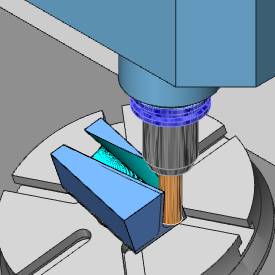
To view the result, on the BobCAMtoolbar, click
Simulation.
This result is a significant reduction ofheavy machine movement for the feature.
Part 12) Add Extensions to the Toolpath
-
Edit the feature and click Parameters.
-
At the bottom of the dialog box, in the Extensions group, type 1.00in both the Start and End boxes.
This extends the lead-in and lead-out by the specified value.(Youcan use these options with or without leads defined for the feature.) -
Compute the toolpath.
This concludes the tutorial.