


Mill Turn Hole Drilling Example
Introduction
This topic provides an example of how to create Mill Drill Hole featuresfor Mill-Turn jobs in BobCAM.First, standard drilling is used to performall face drilling, then cross drilling handles all radial drilling (orX-axis drilling that points to center line), and finally, multiaxis drillingis used to machine all other holes in the model (holes that can't be machinedwith standard or cross drilling.)
Example File
If you are connected to the Internet, the part file for this example can be downloaded automatically by clicking the following link: Mill Turn Drilling Example 1 SLDPRT
Once you download and saved the zip file, extract the files on your system in an easy place to remember.You can then open the file to use with this tutorial.All files for the tutorials in this help system available for download can be found by clicking on the following link: http://www.bobcad.com/helpfiles.
In the example fileprovided, the job, stock, and machine setup are already defined.
Part 1) Create a Mill Hole Feature (Standard Drilling)
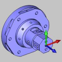
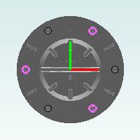
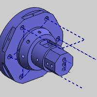
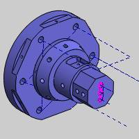
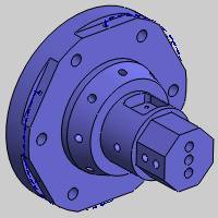
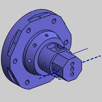
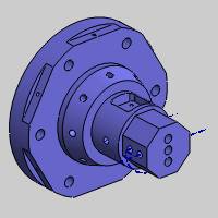
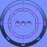
Standard drilling handles all holes in which the tool orientation isparallel to the main spindle direction, which is usually the Z-axis.Formill turn jobs, this is also known as face drilling.This is the firstfeature that we create for our mill turn part.The following image showsthe part and machine setup location.
Set Drilling Type and Select Geometry
-
In the CAMTree, right-click MachineSetup, point to Mill Features,and click Mill Drill Hole.
-
In the Mill Hole Wizard, click SelectGeometry.
The Hole Geometry Selection Manager displays.
Notice the default drilling type is StandardDrill. -
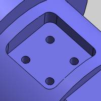
For our standard drilling feature, we selectall cylindrical surfaces so that the software can automatically setthe diameter, top of feature, and feature depth based on our selections.
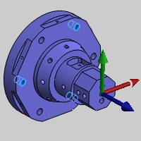
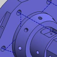
You can click to select the six holes atthe base of the model, and then select the three holes on the front faceof the model.(This order is necessary to obtain the results in the orderthey are described in this tutorial.)
Alternatively, you can select features directlyfrom the Feature Manager Design Tree in the following order: 3/8(0.375) Diameter Hole1, 3/8 (0.375)Diameter Hole2, and 5/16 (0.3125)Diameter Hole1.(You may need to expand the tree in the graphicsarea in order to select the features.)
Note that for this example part and setup,these are the only holes that can be drilled using standard drilling.
-
To confirm the selection, click
 .
.
Notice in the hole list of the Mill HoleWizard, the 0.3750 diameter hole displays as having multiple depths.Clickthe 0.3750 hole in the list andnotice that under Geometry Parameters, only the diameter can be changed.Click the 0.3125 hole in the listand notice the Geometry Parameters now displays the Diameter, Depth, andPick Bottom.
Note: In theGeometry Selection page, when you have more than one depth for a singlediameter, the Depth parameter (and Pick Bottom) becomes unavailable forthat hole size, because it contains more than one hole group.The depthsfor each hole group can always be set in the Feature page of the wizard.
-
Click Next>>.
Define Feature Settings
Notice on the left side of the dialog box that two features are createdfrom our selections: one for each hole diameter.For each feature (diameter),the holes that share the same top of feature and feature depth are automaticallyplaced into a hole group.Because we selected cylindrical surfaces, thesoftware automatically set all of these parameters in the wizard.(Tolearn about selecting other geometry types, view the Pointand Arc Usage Example.) Next we confirm the proper settings for eachhole group.
-
Under HoleGroups, click anywhere in the row of Group 1 to select it.
Notice the hole groups preview displays directlyinside the dialog box.(You may or may not have the same group display,depending on which holes you selected first.)
-
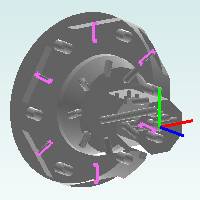
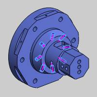
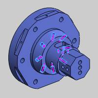
Click and drag in the preview window to rotate the model makingit easier to view the feature preview (shown in pink).
Tip: To modifythe viewing orientation of the hole groups preview, click and drag torotate the view (left or middle mouse button).To pan the view, hold Ctrl and drag with the middle mousebutton.Use the middle mouse button (roll forward or backward) to zoomin or out.
The hole groups preview shows that threeof the lower holes are a single group (same top of feature and featuredepth).The other three holes at the base have a different depth, so theyare placed in a separate group.
-
In the Hole Groups list,click anywhere in the row of Group2 to select it and display the hole groups preview.
Again, we can see that the holes with thesame top of feature, feature depth, and diameter are placed into a holegroup.For now, we don't need to make any changes to the hole groups.
-
Click Next>>.
Define the Machining Strategy and Tool Data
-
Under Template,click Hole.
Selecting this operation template adds one Center Drill and one Drilloperation to the Current Operations list. -
On the lower-left side of the dialog box,click Apply to All Features.
This assigns the same operation template to the Machining Strategyof the second feature. -
Click Next>>.
For this example, we don't make any changes to the Posting or MultiaxisPosting settings, but notice the Posting Mode and Submachine groups.The Posting Mode determines how the machine performs the operationsand how the code is output.With Auto/Y-axis mode, the spindle (C-axis)remains fixed and the milling spindle uses the Y-axis travel to movearound the part (because we are using a machine that has Y-axis capabilities).The Submachine list is used to change the submachine from the defaultsubmachine that is selected under the Machine Setup in the CAM Tree. -
In the tree under the first Center Drilloperation, click
 Center Drill.
In the example file provided, the Tool Cribwas pre-loaded with all tools for the job.The software searches the ToolCrib to find a matching tool for the operation.Loading the Tool Cribfirst can save significant time during feature creation.
There are some situations in which the softwarecannot automatically select the appropriate tool, for example, when thereare multiple tools with similar parameters.To illustrate how to assigntools from the tool crib manually, click the ToolCrib button.
Notice that 5Center Drill is already selected in the device tree and the toolslist.This is the desired tool, so we just click OKto assign close the Tool Crib and assign the tool to the current operation.
Important: Whenopening the Tool Crib from the CAM Wizards, the tool that is selectedwhen you click OK is assigned to the operation.Even though we pre-loadedthe tool crib, you can still add and mount tools at any time.You canwork to your own preferences, but be sure to select the appropriate tool,for the current operation, in the device tree or the tools list beforeyou click OK.
-
Click Next>>.
No changes are made to the center drill parameters, but notice thereare no hole groups listed.Center drill and chamfer operation parametersare applied to all hole groups in the feature, but all other drillingoperations have hole-group specific parameters as shown later. -
Click Next>> twiceto go to the Drill operation tool settings and notice again that SystemTool is used to automatically assign our drill tool information fromthe Tool Crib.
-
Click Next>>.
Define Operation Parameters for Hole Groups
It is important to understand how to set the operation parameters forhole groups.As shown previously, operations such as center drill andchamfer use shared parameters for all hole groups, but all other operationscontain a hole groups list so you can set the parameters separately foreach group.
-
Notice the Use Cutting Conditions check boxis selected.We use this option to allow the software to automaticallycalculate the effective depth and overall depth values for all holegroups.
It is important that you set the parameters for each hole group byselecting a group before making changes. -
Under HoleGroups, click to select Group1 (it highlights in dark blue).
-
Under CycleType, click Peck.
-
Click to select Group2 in the Hole Groupslist.
Notice that pecking is not selected for this group because we havenot changed it yet. -
Under CycleType, click Peck.
Both hole groups now use the same settings. -
On the left, click Feature-0.3125-Blind.
Define the Second Feature
The second feature in the tree was created for the other hole diameterwe selected.Next we define the settings for this feature.
-
Under HoleGroups, click to select Group1.
The hole groups preview displays so we can confirm with which holegroup we are working.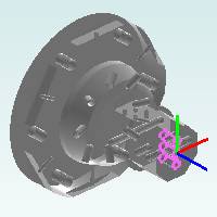
-
No changes are needed to the hole group parameters,because they were automatically set from selecting cylindrical surfaces.
Sometimes you need to modify the parameters for a hole group.The followingsteps explain how.
Editing Values in the Hole Groups Table
In the Hole Groups list, you can click anywhere in the row of a groupto select the group, but if you click the name, top of feature, or featuredepth value directly, it becomes available for editing (and the groupis selected).When adding and removing selections in the Hole Groups list,you should click the far left side of the row (anywhere in the Numbercolumn).
-
Under HoleGroups, click the name Group1.
Notice that the text is selected and available for editing. -
Type 0.3125Top, and press Enter or click anywhere else to update the name.
Creating custom names for hole groups can be very helpful when thereare many hole groups in a feature.The group names display in theparameters page for each operation, so descriptive names can makeit easier to set the parameters for many hole groups. -
You can also click the Top of Feature valueor the Feature Depth value directly to edit it in the table (no changesare needed for this example).
-
Click Next>>.
Finish the Feature and Compute the Toolpath
-
Notice the Machining Strategy is set to theHole operation template, because we used Apply to All Features earlier.
-
In the tree on the left, under the last Drill operation, click Parameters.
Under Hole Groups, click toselect 0.3125 Top.(Noticethis is using our custom group name.) -
Under CycleType, click Peck.
-
Click Computeto calculate the toolpath.
Part 2) Understanding the Toolpath for Hole Groups
After computing the toolpath, we can see that it needs modified forone feature.It is important to understand how the material approach settingsare applied to hole groups.The rapid plane is applied withinhole groups and the rapid movement betweenhole groups is determined by the group retracts.Currently the tool movementwithin groups (rapid plane) is going through the model because we areusing a Z-axis plane.This is easily resolved in the following steps.
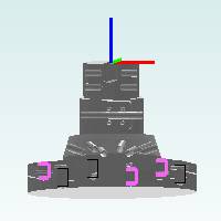
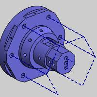
The toolpath result is shown next.
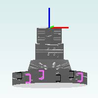
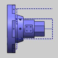
The rapid movement through the part is shown next.
Notice that the rapid movement between hole groups retracts to a planein front of the part, instead of using the rapid plane.This movementis defined by the group retracts.In the next part of this tutorial, webreak the hole groups so that rapid movement between all holes uses thegroup retracts.
Part 3) Break Hole Group and Group Retracts
Next we edit the first feature to modify the hole groups and use ourgroup retracts to customize the toolpath for our example part.
-
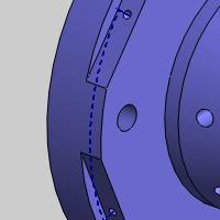
In the CAMTree, click the first feature name StandardFeature Mill Hole - 0.3750.
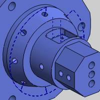
Notice the feature highlight displays inthe graphics area.This is an easy way to confirm the feature with whichwe are working.
Click the name of the second feature, Standard Feature Mill Hole - 0.3125,to highlight it in the graphics area.
No changes are needed for our second feature.
-
Right-click Standard FeatureMill Hole - 0.3750, and click Edit.
-
Under Hole Groups, (Group2 may already be selected, but if not, click to select it first) holdShift and click Group1 so that both groups are selected.
Click Break Hole Group.
Notice there are now six groups.These groups each contain only a singlehole, and the naming shows which group they came from (Group 1.1,Group 1.2, and Group 1.3 came from Group 1).
You can click each group in the list to display the hole groups previewand confirm the changes. -
Under Material Approach,click Group Retracts.
The group retracts determine the rapid movement used between hole groups,so all of our hole groups now use the group retracts instead of therapid plane. -
Confirm that Plane isselected and change the Heightvalue to 0.6250.
Click OK. -
Click Compute to updatethe toolpath.
After viewing the new toolpath, we edit thefeature again, and change the group retracts Heightvalue to -3.000.Note that thisvalue is in reference to the machining origin coordinate system (whichis at the front face of our part).The computed result is shown next.
To hide all toolpath created thus far, right-clickMachine Setup, and click Blank/Unblank Toolpath.
This concludes the standard drilling portionof this tutorial.Next we create a feature using cross drilling to machinethe drill holes in which the tool orientation (on the physical machine)is parallel to the X-axis and points to center line.Note that any X-axisdrill holes that don't point to (or cross) the center line of the partrequire multiaxis (Y-axis) mill turn machines as shown later.
Part 4) Create a Mill Hole Feature (Cross Drilling)
Set Drilling Type and Select Geometry
-
Right-click MachineSetup, point to Mill Features,and click Mill Drill Hole.
-
Click SelectGeometry.
-
Next to Standard Drill, click the down arrow,and select Cross Drill.
Important: Noticethe Rotation Axis parameter.Thismust be set to the rotational axis of the part on the machine, which isusually Z Axis, as it isfor this example.
In the standard drilling portion of thistutorial, we explained that you can select surfaces directly from themodel or use the Feature Manager Design Tree to select the CAD features.Next we show you an even more efficient method of selecting geometry.
-
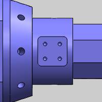
Under Geometry, clickthe Select Whole Bodies checkbox, and click the model in the graphics area.
Using Select Whole Bodies allows the softwareto analyze the model and automatically create features.This works verywell for most situations, but notice the Options group at the bottom ofthe Selection Manager.You can always use the minimum and maximum holediameter values to make the software avoid certain holes sizes.This canbe very helpful for more complex models or when the desired features arenot created.
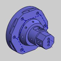
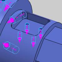
Note that the holes inside of the pocketcannot be drilled using cross drilling, because these holes do not pointto center line, thus they require Y-axis (multiaxis) movement.This isalso true for the angled holes, although they require full 5-axis movement.These holes are machined later in the multiaxis portion of this tutorial.
Tip: The softwareautomatically filters the geometry selections for each drilling type basedon the hole orientation (and machining origin).Even if you selected themultiaxis holes shown in the previous images, they would be filtered outwhen you confirm the selections.
-
Click
to finish geometry selection.
Notice in the Holes list, each hole size, depth, and through hole statusdisplay from the selected features. -
Click Next>>.
Define the Features and Compute Toolpath
-
Under HoleGroups, select Group 1to display the hole groups preview.
For now, we do not change any feature settings. -
Click Next>>.
-
Under Template,click the Hole operation template,and click Apply to All Features.
-
In the tree on the left, click Feature-0.2500-Through.
Under Hole Groups, click Group 1to display the preview and confirm with which hole we are working.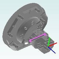
Although all holes on the front of the model are 0.250 inch diameter,the through hole and blind holes become separate features becausethey require different depth calculations for the toolpath. -
Click Feature-0.1250-Blindand select Group 1 to previewthe grouping of holes.We can see that the software correctly detectedall cross drill holes in the model and created features for them withthe parameters already assigned in the Mill Hole Wizard.
No other changes are made at this point.For this example, we computethe toolpath first to check for any changes that need made. -
Click Compute.
Next we hide the toolpath of two features so we can focus on one ata time. -
Right-click the first feature, CrossFeature Mill Hole - 0.250, and click Blank/UnblankToolpath.
Repeat this step to hide the toolpath ofthe second (0.250) cross drill feature in the CAM tree.
We can see that the toolpath for the lastfeature retracts above the flats, but has minimal clearance to the outerdiameter of the part.
To add more clearance for these holes, wedon't want to break the hole group, because we only need to increase therapid plane value.(The rapid movement between these holes uses the rapidplane and not the group retracts, because this is a single hole group.)
Edit the Feature and Rapid Plane
-
Right-click CrossFeature Mill Hole - 0.1250, and click Edit.
-
Under MaterialApproach, change the RapidPlane value to 0.3000.
-
Click Compute.
The toolpath now has more clearance to the outside of the part.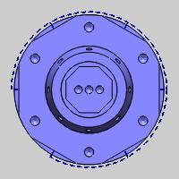
-
Right-click CrossFeature Mill Hole - 0.1250, and click Blank/UnblankToolpath to hide it.
Edit Feature and Group Retracts
-
Right-click CrossFeature Mill Hole - 0.2500, and click Blank/UnblankToolpath.
-
Repeat the previous step to show the toolpathfor the second (0.250) cross drill feature.
For the last two cross drill features, the toolpath is acceptable,but we want to make a few changes.In the toolpath for the blind holes,the rapid plane is properly clearing the flats on the front of themodel when moving from one side to the other (within groups) so nochange is needed.The retract distance between hole groups (groupretracts) however, can be reduced. -
Right-click the first CrossFeature Mill Hole - 0.2500, and click Edit.
-
Click GroupRetracts, and change the Radiusvalue to 2.000.
Note: Noticethat BobCAM automatically selected the cylindrical group retract type,because we are creating cross drill features.
Click OK.
-
Click Compute.
-
Repeat the previous three steps for the other (0.250) crossdrill feature.
We made this change simply to reduce the amount of tool movement betweenoperations and make a more efficient toolpath. -
Hide the toolpath for both 0.250 cross drill features.
Next we create a multiaxis hole feature todrill the remaining holes in our example part.
Part 5) Create a Mill Hole Feature (Multiaxis Drilling)
Set Drilling Type and Select Geometry
-
Right-click MachineSetup, point to Mill Features,and click Mill Drill Hole.
-
Click SelectGeometry.
-
Next to Standard Drill, click the down arrow,and select Multiaxis Drill.
Important: Beforeselecting geometry, it is important to understand that multiaxis drillingcan perform all of the drilling we created in this tutorial.For thisreason, this is a situation where we don't want to use the Select WholeBodies option, because the software will create features for all holesin the model.Instead, we select only the holes that require multiaxisdrilling using their corresponding CAD features.
-
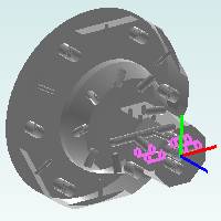
In the Feature Manager Design Tree, click to select the followingfeatures in the order listed: 1/4(0.25) Diameter Hole3, CirPattern3,and 1/8 (0.125) Diameter Hole1.
-
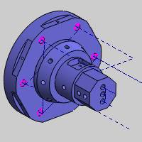
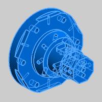
Now that all holes are selected, we need to confirm that thedrilling direction is correct for all holes (the direction indicatorpoints to the bottom of the hole).
We can see that the drilling direction is correct for all holes.Thesoftware uses the center of the selected geometry to set the drillingdirection, which for this part works perfectly.You may sometime needto reverse the direction when it is incorrect or when using othergeometry types.To reverse the direction of one or more holes, selectthem in the Holes list (the direction indicator of the selected holeschanges color in the graphics area), and click (Reverse).
 -
Click
to close the Selection Manager.
Notice in the holes list that the parameters are already properly setbased on our geometry selections. -
Click Next>>.
Define the Feature Settings
-
Under HoleGroups, select Group 1by clicking in the Numbercolumn.
The hole groups preview displays. -
Press the down arrow key to move throughthe groups and update the preview.
Notice each group contains a single hole.This is because each oneof these holes has a different tool vector.Multiaxis hole groupsmust also share the same tool vector in addition to the diameter,top of feature, and feature depth. -
Click GroupRetracts.
Next to Type, click the downarrow, and select Cylinder.
Change the Radius value to2.000.
Click OK. -
On the lower left, click ApplyMaterial Approach to All so that both features use the samegroup retracts, rapid plane, and feed plane.
-
Click Next>>.
-
Select the Holeoperation template, and click Applyto All Features.
Note that we are again using many default settings to compute the toolpath.This is done only to reduce the length of the tutorial.You shouldalways confirm or select all settings in the wizard when creatingyour own programs.You can get more information about all wizard parametersusing this help system. -
Click Compute.
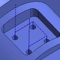
Note that the four holes at the bottom ofthe pocket require a mill-turn machine with Y-axis capabilities (4-axis).The angled holes in our other multiaxis feature require a multiaxis (5-axis)mill turn machine.We are currently using the BC 2T2S 5X machine whichcan handle all drilling creating in this tutorial.
This concludes the tutorial.