


 Leads
Leads
Introduction
Leads are an additional move added to the start and end of the cut. The Leads page handles both lead-in and lead-out moves for the Groove Finish operation. This topic explains the lead parameters that are used for the Groove Finish operation.
Lead-in
The Lead-in is an additional move prior to the initial cut into the material. The Lead-in allows you to specify how the cut is approached.
- Parallel
- creates a lead into the material that is parallel with the
toolpath move it is preceding.
- Perpendicular
- creates a lead into the material that is perpendicular to
the toolpath move it is preceding.
- Horizontal
- creates a lead into the material that is parallel to the
center of rotation.
- Vertical
- creates a lead into the material that is perpendicular to
the center rotation.
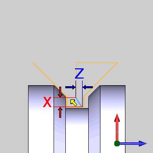
- Angle
- creates a lead into the material that is at a 45 degree angle.
- Custom
- creates a lead into the material that is dictated by the
values entered in the Lead-in Z, and Lead-in X boxes.
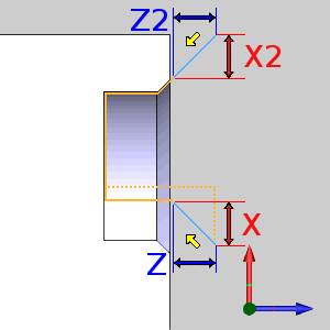
- Lead-in
Z - sets the distance and direction of travel, in the Z-axis,
for the approach into the toolpath.
- Lead-in
X - sets the distance and direction of travel, in the X-axis,
for the approach into the toolpath.
- Lead-in
Z - sets the distance and direction of travel, in the Z-axis,
for the approach into the toolpath.
-
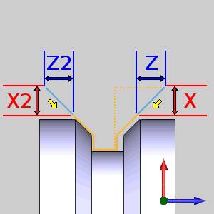
 Override Z2/X2 - When the Force
Down Cutting pattern is in use, there are actually two lead-ins to
the feature. By default, these values are adjusted so the one side
is a mirror of the other. Selecting this option will allow the Lead-in
Z2, and Lead-in X2 variables to be adjusted by the user.
Override Z2/X2 - When the Force
Down Cutting pattern is in use, there are actually two lead-ins to
the feature. By default, these values are adjusted so the one side
is a mirror of the other. Selecting this option will allow the Lead-in
Z2, and Lead-in X2 variables to be adjusted by the user.- Lead-in Z2 - sets the distance and direction of travel in the Z-axis for the other approach into the toolpath.
- Lead-in X2 - sets the distance and direction of travel, in the X-axis, for the other approach into the toolpath.
- Lead-in Z2 - sets the distance and direction of travel in the Z-axis for the other approach into the toolpath.
Lead-out
The Lead-out is an additional move following the last cut in the material. The Lead-out allows you to specify how the tool exits the cut.
- Parallel
- creates a lead out of the material that is parallel with
the toolpath move preceding it.
- Perpendicular
- creates a lead out of the material that is perpendicular
to the toolpath move preceding it.
- Horizontal
- creates a lead out of the material that is parallel to the
center of rotation.
- Vertical
- creates a lead out of the material that is perpendicular
to the center rotation.
- Angle
- creates a lead out of the material that is at a 45 degree
angle.
- Custom
- creates a lead out of the material that is dictated by the
values entered in the Lead-out Z, and Lead-out X boxes.
- Lead-out
Z - sets the distance and direction of travel, in the Z-axis,
for the approach into the toolpath.
- Lead-out X - sets the distance and direction of travel, in the X-axis, for the approach into the toolpath.
- Lead-out
Z - sets the distance and direction of travel, in the Z-axis,
for the approach into the toolpath.
Note: The lead-ins and lead-outs for Grooving operations are always adjusted based on the feature and region selected. This means that in most cases you can type positive values and the resulting leads are exactly what is needed to exit the cut. Negative values are still supported and can be used in situations where the adjusted leads do not yield the proper results.
Next Topic
After defining the leads for the last operation in the wizard, click Compute to close the wizard and create the toolpath. If you are in a Mill Turn job, click Next> > to go to the MDI page.