


 Patterns
Introduction
This topic explains the Patterns page of the 4 Axis Advanced Rough operation found in the Mill 4 Axis Rotary Wizard.
 Patterns
Cut Pattern
-
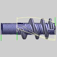
 Zig - sets the cutting
method to one-way. All cutting feed moves share the same direction.
Zig - sets the cutting
method to one-way. All cutting feed moves share the same direction.
-
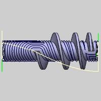
 Zig Zag - sets the cutting pattern to alternate
directions. Each toolpath segment changes cutting direction along
the part.
Zig Zag - sets the cutting pattern to alternate
directions. Each toolpath segment changes cutting direction along
the part.
-
Type - defines the general cutting type of the toolpath. Select from one of the following options.
-
Offset - creates a toolpath pattern that is an offset pattern of the area being cut.
-
Offset and Spiral - creates a toolpath pattern that is an offset pattern of the area being cut, except for the areas where spirals can be created without collision. Where spirals can be created without collision, spirals are used.
-
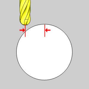
SideShift - defines a distance that the tool is shifted away from the center of the rotary axis. When a side shift is applied, the tool does not point directly to the rotary axis. This can be used to minimize cutting with the center of the tool (or to cut with the front of the tool).
Rotary Axis
You must select the Rotary Axis being used for the feature, which includes the Direction and the Base Point.
Important: The Rotary Axis Direction and Base Point parameters are used for the toolpath creation and are not necessarily the same as the machine's rotary axis.
Select the proper axis for the part orientation:
-
X Axis - Rotation around the X Axis.
-
Y Axis - Rotation around the Y Axis.
-
Z Axis - Rotation around the Z Axis.
-
User Defined - Rotation to be defined manually with the Direction values below.
-
 - opens the Re/Select Geometry dialog to allow you to define the location of the Rotary Axis.
 -
Method - Choose between Pick a line, or Pick two points. The Selected Geometry group will then allow you to select a line, or a Start Point and an End Point.
-
-
Direction - displays the direction vector for the selected rotary axis. The XYZ values are automatically updated when you select X Axis, Y Axis, or Z Axis. For example, rotation around the X-axis is defined by the vector X1Y0Z0. When selecting User Defined, the Direction XYZ values become available for you to define a custom rotary axis direction vector.
-
Base Point - is used to define the distance from the Machine Setup (machining origin) to the rotary axis of the part. If the Machine setup is aligned with the rotary axis of the part, the Base Point values should be X0Y0Z0 (for most scenarios). As another example, if you set the Machine Setup to the top of a four-inch cylinder, you define the Base Point as X0Y0Z-2.

Cut Direction
You can define the cutting direction as:
-
Clockwise - based on the right-hand
rule of the selected rotary axis direction.
-
Counterclockwise - based on the
right-hand rule of the selected rotary axis direction.
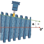
Conical Machining
![]() - The tool remains flat along the rotary axis.
- The tool remains flat along the rotary axis.
![]() - With this check box selected, the tool and toolpath can be adjusted to be angled to match the angle of conical parts.
- With this check box selected, the tool and toolpath can be adjusted to be angled to match the angle of conical parts.
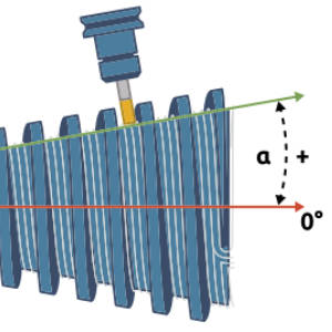
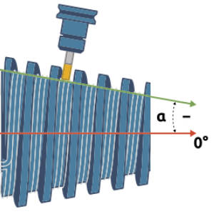
- Cone Angle - Allows you to set the angle of the cone based on an angle and positive rotary axis direction.
Positive Cone Angle Negative Cone Angle 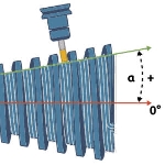
 - Opens the Re/Select geometry dialog allowing you to select a line or two points to dictate the angle of the conical machining.
Related Topic
Click Next> > to move on to the Parameters page.