the Start Point Parameters Dialog Box
Introduction
This topic will explain the options in the start point parameters dialog, explain where to find it, and provide examples of how it works.
The Start Point
The start point defines the start position of the first cut and for the following cuts on the drive surface. This point can be set by one of two options.
Navigation
To access the Start Point Parameters dialog box:
- In the Surface Paths tab
under Sorting, select the
 Start
Point check box.
Start
Point check box.
- Click Start Point.
The Dialog Box Parameters
Set Point By
-
 Position- select this option to set the start
point by position. Click
Position- select this option to set the start
point by position. Click  to open the Position dialog box. You can type coordinate values,
or click to
select geometry.
to open the Position dialog box. You can type coordinate values,
or click to
select geometry. -
 Surface
Normal Direction - select this option to set the start
point by the surface normal direction. Click
to open the Surface Normal Position dialog box. You can type coordinate
values, or click
to select geometry. The start point is defined by a vector. The
point of the toolpath which has its surface normal direction closest
to the vector defines the new start point.
Surface
Normal Direction - select this option to set the start
point by the surface normal direction. Click
to open the Surface Normal Position dialog box. You can type coordinate
values, or click
to select geometry. The start point is defined by a vector. The
point of the toolpath which has its surface normal direction closest
to the vector defines the new start point.
Start Point Will Be Applied in Subsequent Cuts as Following
This group controls how the start point is used for any toolpath cuts after the first. You can use one of the three following options.
-
Shift by Value - type a value
for the distance that shifts the start point for the next toolpath
pass. The start point shifts for each pass.
-
Rotate by [Deg] - type a value
in degrees that shifts the start point for the next toolpath pass.
The start point rotates for each pass.
-
Minimize
Surface Normal Change - used
mainly for blisk blades, this option keeps the start point consistent,
for example on a curved edge with a tight radius.
Important:
► The start point cannot be shifted
or rotated on open contours nor
rotated on flat surfaces.
► Selecting a start point does not change the
machining order, even if the selected point is closer to the last
lane than the first. It is only set for the first contact point
on the first calculated toolpath slice. If the order of the toolpath
slices should be changed, the option Cut Order or Flip Step Over
should be used.
► When using a Start Point Shift, the start
point is shifted along the cutting direction. For Zig Zag, the
start point shifting also alternates its direction as well.
► The position values are absolute X-,Y-, and
Z-coordinates.
► The angle values are relative to previous
cut. Value in degrees.
Using Start Point
Once the start point is defined it is very important to understand how the next start point is applied. This depends on one of two options: Cutting Method or Toolpath contour.
How it Works - Start Point
The following images describe different scenarios with combinations of cutting methods and surfaces with open or closed contours.
-
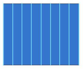
The first scenario shows an open surface contour with parallel cuts.
-
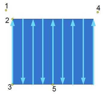
The default start point is defined by the toolpath pattern. The image shows that the Cutting Method is set to Zig Zag and the machining starts at position 3 by default.
-
If a new start point is set at position 5 then the machining starts from the initial start point (position 3). The new start point cannot change the order of the cuts. So the machining won't start from the middle.
-
If a new start point is set at position 1, 2, or 4 then the starting point for the machining is position 2. The machining now swaps and starts from the opposite side. Again, a new start point doesn't change the cut order, just the start position on the initial surface edge.
-
The next scenario shows the same surface but this time the Cutting Method is set to One Way. In this case it doesn't matter which start point is selected, the start point is always at position 3.
-
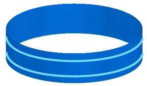
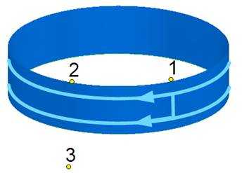
The next scenario shows a closed surface contour with parallel constant Z-cuts. The cuts are closed contours so that means that the cuts end where they started.
-
The Cutting Method is set to One Way. The standard start point would be at position 1.
-
Now the new start point is set to position 2. Accordingly, the start point moves to position 2.
-
If the new start point is set to position 3 then machining starts at position 2. The reason is the same as before, when the start point is changed only the start position on the initial start edge changes, not the cut order.
How it Works - Shift/Rotate Start Point
-
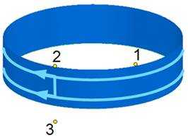
The first scenario shows a closed contour with constant Z-cuts using One Way. Shift By Value is set to 1 unit. In this case the start point is shifted by 1 unit at every complete rotation.
-
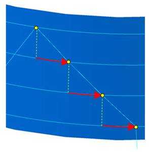
The shifting is done along the toolpath. In the next image, the red arrows represent the shifting, and the yellow dots represent the start points.
-
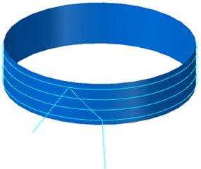
The second scenario shows a closed contour with constant Z-cuts using One Way. Rotated By[Deg] is set to five degrees. In this case the start point is rotated five degrees at every complete rotation.
-
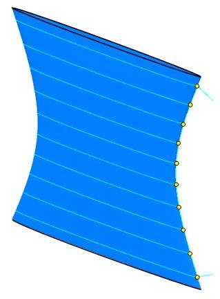
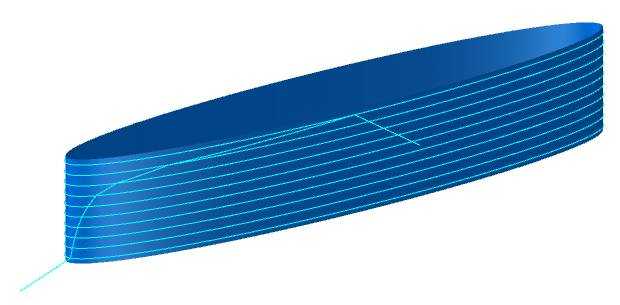
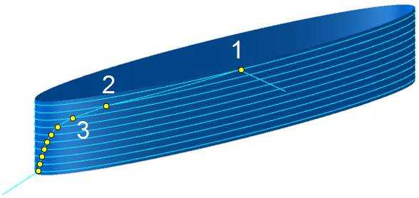
Every new start point position is calculated based on the surface normal direction. That means that in the area where the surface radius is large, the start points are spread (position 1, 2, and 3). In the area where the surface radius become smaller, the surface normal direction becomes bigger, so the start point positions are much closer to each other.
-
If the radius of the surface is infinite, that means the surface is flat, a rotational start point doesn't work.
How it Works - Minimize Surface Normal Change
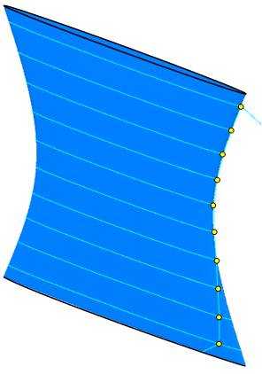
This option is used for blisk blades or turbine blades machining. In this case it is desired to have a start point at the small radius of the wing. Unfortunately the start points move by themselves and leave the edge position. To avoid this they can be forced to be always at a position with the same surface normal direction. In this way the start points always stay at the edge.
-
The new start point was picked in the upper left corner. The resulting toolpath with a new start point appears as shown next. In the lower section the toolpath start points are moving away from the edge into the wall face.
-
With Minimize Surface Normal Change activated the start point stays at the point with the same surface normal direction, which means on the edge of the wing.