


The Automatic Length and Diameter Cycle
Introduction
This topic will explain the Automatic Length and Diameter cycle, will describe how to access it, will explain the options found in it, and will explain how to use it with quick steps.
The Automatic Length and Diameter Cycle
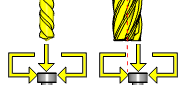
This cycle combines the automatic length measuring cycle and the automatic diameter measuring cycle.
Length and radius values are written into the tool offset register. The wear registers are zeroed and the values are placed in the geometry registers.
Navigation
To access the Automatic Length and Diameter cycle:
- In the CAM Tree, right-click Milling Tools, and select Tool Crib.
The Tool Crib dialog launches in the Data Entry Manager. - Add all tools needed for the job.
- Click OK.
The Tool Crib dialog closes. - In the CAM Tree, locate the desired Machine Setup for the Probing cycle, right-click the Machine Setup, and select Probing.
The Probing dialog launches in the Data Entry Manager. - In the Machining Strategy list of the Feature page, click the Contact Tool Setter operation.
The Contact Tool Setter operation replaces the Measure operation in Current Operations list. - Click the Operations(s) tab.
- Select the appropriate cycle from the drop down list in the Cycle section of the Parameters tab.
The Data Entry Parameters
Parameters
Tool
- Tool Name -
This drop down will list all the tools currently in the tool crib.
- Override Tool Data
 - With this check box selected, you will be able to update the Tool Number and Tool Diameter.
 - With this check box cleared, editing of the Tool Number and Tool Diameter is unavailable.
 - Tool Number - Lists the Tool Number of the currently selected tool.
- Tool Diameter - Lists the diameter of the currently selected tool.
Options
- Tool Offset - Tool length offset number. This is the offset location in which the measured tool length is stored when it needs to be different from the active tool number.
- Approx. Tool Length - Reference length of the calibration tool.
- Tolerance - When this input is used, the tool offset is not updated if the tool length is found to be out of tolerance.
- Broken Tool Flag - Tool out of tolerance flag. Use this flag to prevent a tool OUT OF TOLERANCE alarm from being raised. Enter the value to be called out with the flag.
- Overtravel Distance - The default overtravel distance and radial clearance. Overtravel is the distance beyond the point at which contact should have been made with the stylus the tool is permitted to move before an out of tolerance alarm is initiated.
- Additional Z Clearance - sets a particular height above the stylus at which the tool should travel when moving from side to side.
- Z Measure Position - sets how far down from the top of the stylus contact should be made to take the diameter measurements.
- Experience Value (Diameter) - This value is the difference between the measured radius/diameter of the tool and the actual radius/diameter when the tool is under load during the cutting process. It is used to refine the measured radius/diameter, based on previous experience of how the effective radius/diameter differs from the measured radius/diameter when the tool is under load.
- Experience Value (Length) - Experience value for the length. This value is the difference between the measured length of the tool and the effective length when the tool is under load during the cutting process. It is used to refine the measured length, based on previous experience of how the effective length differs from the measured length when the tool is being used.
-
Diameter Offset - determines the diameter offset to update in the cycle. By default this value matches the current tool number.
Quick Steps - Automatic Length and Diameter
- In the CAM Tree, right-click Milling Tools, and select Tool Crib.
The Tool Crib dialog launches in the Data Entry Manager. - Add all tools needed for the job.
- Click OK.
The Tool Crib dialog closes. - In the CAM Tree, locate the desired Machine Setup for the Probing cycle, right-click the Machine Setup, and select Probing.
The Probing dialog launches in the Data Entry Manager. - In the Machining Strategy list of the Feature page, click the Contact Tool Setter operation.
The Contact Tool Setter operation replaces the Measure operation in Current Operations list. - Click the Operations(s) tab.
- Select the appropriate cycle from the drop down list in the Cycle section of the Parameters tab.
- In the Parameter section, select the tool and adjust the select the Override Tool Data check box is necessary.
If you select the Override Tool Data check box, adjust the Tool Number and Tool Diameter values as needed. - In the Options section, select the check boxes for any and all calls required in the output and set their values as needed.
- Select the Raw Text tab in order to output any macros or code manually.
- In the Raw Text tab, select the Output in NC Program check box.
- Enter the data to be output in the text field.
- Click OK.
The operation is added to the CAM Tree.
Example 1 - Automatic Length and Diameter On Center
When setting the Automatic Length and Diameter the two main choices are whether to keep the tool centered on the beam or not.In this example we will keep the tool centered on the beam.
In this example we:
- Setup the Tool Crib
- Select the Automatic Length and Diameter cycle.
- Select the tool.
Part 1) Setting up the Tool Crib
- In the CAM Tree, right-click Milling Tools, and select Tool Crib.
The Tool Crib dialog launches in the Data Entry Manager. - Add all tools needed for the job.
- Click OK.
The Tool Crib dialog closes.
Part 2) Selecting the Automatic Length and Diameter cycle
- In the CAM Tree, locate the desired Machine Setup for the Probing cycle, right-click the Machine Setup, and select Probing.
The Probing dialog launches in the Data Entry Manager. - In the Machining Strategy list of the Feature page, click the Contact Tool Setter operation.
The Contact Tool Setter operation replaces the Measure operation in Current Operations list. - Click the Operations(s) tab.
By default the Automatic Length and Diameter is the selected cycle.
Part 3) Selecting the Tool to be set
- In the Parameters section, select the tool to be set from the drop down list.
By default the Tool Offset is set to the tool number of the selected tool. - Click OK to create the Automatic Length and Diameter cycle and exit the dialog.
Example 2 - Automatic Length and Diameter Off Center
When setting the Automatic Length and Diameter the two main choices are whether to keep the tool centered on the beam or not. In this example we will move the tool off center of the beam.
In this example we:
- Setup the Tool Crib.
- Select the Automatic Length and Diameter cycle.
- Select the tool.
- Set the Radial Stepover
Part 1) Setting up the Tool Crib
- In the CAM Tree, right-click Milling Tools, and select Tool Crib.
The Tool Crib dialog launches in the Data Entry Manager. - Add all tools needed for the job.
- Click OK.
The Tool Crib dialog closes.
Part 2) Selecting the Automatic Length and Diameter cycle
- In the CAM Tree, locate the desired Machine Setup for the Probing cycle, right-click the Machine Setup, and select Probing.
The Probing dialog launches in the Data Entry Manager. - In the Machining Strategy list of the Feature page, click the Contact Tool Setter operation.
The Contact Tool Setter operation replaces the Measure operation in Current Operations list. - Click the Operations(s) tab.
By default the Automatic Length and Diameter is the selected cycle.
Part 3) Selecting the Tool to be set
- In the Parameters section, select the tool to be set from the drop down list.
By default the Tool Offset is set to the tool number of the selected tool.
Part 4) Setting the Radial Stepover
- In the Options section, select the check box for Radial Stepover.
- Update the Radial Stepover value to reflect the distance from the center of the tool at which the measurement should be taken.
- Click OK to create the Automatic Length and Diameter cycle and exit the dialog.
Example 3 - Automatic Length and Diameter with Experience Values
In some cases, after operations have been run, probing the part reveals a variation in the required depth of the part, this can be caused by the forces of the job compressing the tool slightly. When probing operations reveal these discrepancies in depth, it can be necessary to account for them when setting the length of the tool.
In this example we:
- Setup the Tool Crib.
- Select the Automatic Length and Diameter cycle.
- Select the tool.
- Account for tool compression/deflection with Experience Value.
Part 1) Setting up the Tool Crib
- In the CAM Tree, right-click Milling Tools, and select Tool Crib.
The Tool Crib dialog launches in the Data Entry Manager. - Add all tools needed for the job.
- Click OK.
The Tool Crib dialog closes.
Part 2) Selecting the Automatic Length and Diameter cycle
- In the CAM Tree, locate the desired Machine Setup for the Probing cycle, right-click the Machine Setup, and select Probing.
The Probing dialog launches in the Data Entry Manager. - In the Machining Strategy list of the Feature page, click the Contact Tool Setter operation.
The Contact Tool Setter operation replaces the Measure operation in Current Operations list. - Click the Operations(s) tab.
By default the Automatic Length and Diameter is the selected cycle.
Part 3) Selecting the Tool to be set
- In the Parameters section, select the tool to be set from the drop down list.
By default the Tool Offset is set to the tool number of the selected tool.
The available tools in this list are pulled directly from the Tool Crib.Tools mu
Part 4) Using the Experience Values
- In the Options section, select the check box for Experience Value (Diameter).
- Update the Experience Value (Diameter) value to reflect the depth variation found in the probing cycle.
This value will be added to the Diameter found by the tool setter cycle. - In the Options section, select the check box for Experience Value (Length).
- Update the Experience Value (Length) value to reflect the variation found in the probing cycle.
This value will be added to the Length found by the tool setter cycle. - Click OK to create the Automatic Length and Diameter cycle and exit the dialog.
Tip: To learn about how to use the Broken Tool Flag option, see the examples in the Broken Tool - Plunge and/or Broken Tool - Solid topics.