


The Automatic Length, Feed Up Cycle
Introduction
This topic will explain the Automatic Length, Feed Up cycle, will describe how to access it, will explain the options found in it, and will explain how to use it with quick steps.
The Automatic Length, Feed Up Cycle
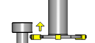
This cycle is used to measure the effective length of the back edge of a rotating tool, such as a slitting saw, back boring bar or internal groove tool.
The cycle automatically moves the tool to the initial clearance position above the stylus and then to the correct position for measurement, before feeding to the secondary clearance position prior to the measurement move.
After measurement, the tool returns to the home position in the Z axis. Where space is restricted from the outer radius of the tool to position under the stylus, a U input can be used to limit the distance that the tool point will position from the edge of the stylus.
Navigation
To access the Automatic Length, Feed Up cycle:
- In the CAM Tree, right-click Milling Tools, and select Tool Crib.
The Tool Crib dialog launches in the Data Entry Manager. - Add all tools needed for the job.
- Click OK.
The Tool Crib dialog closes. - In the CAM Tree, locate the desired Machine Setup for the Probing cycle, right-click the Machine Setup, and select Probing.
The Probing dialog launches in the Data Entry Manager. - In the Machining Strategy list of the Feature page, click the Contact Tool Setter operation.
The Contact Tool Setter operation replaces the Measure operation in Current Operations list. - Click the Operations(s) tab.
- Select the appropriate cycle from the drop down list in the Cycle section of the Parameters tab.
The Data Entry Parameters
Parameters
Tool
- Tool Name -
This drop down will list all the tools currently in the tool crib.
- Override Tool Data
 - With this check box selected, you will be able to update the Tool Number and Tool Diameter.
 - With this check box cleared, editing of the Tool Number and Tool Diameter is unavailable.
 - Tool Number - Lists the Tool Number of the currently selected tool.
- Tool Diameter - Lists the diameter of the currently selected tool.
Options
- Tool Offset - Tool length offset number. This is the offset location in which the measured tool length is stored when it needs to be different from the active tool number.
- Approx. Tool Length - Reference length of the calibration tool.
- Tolerance - When this input is used, the tool offset is not updated if the tool length is found to be out of tolerance.
- Broken Tool Flag - Tool out of tolerance flag. Use this flag to prevent a tool OUT OF TOLERANCE alarm from being raised. Enter the value to be called out with the flag.
- Overtravel Distance - The default overtravel distance and radial clearance. Overtravel is the distance beyond the point at which contact should have been made with the stylus the tool is permitted to move before an out of tolerance alarm is initiated.
- Experience Value (Length) - Experience value for the length. This value is the difference between the measured length of the tool and the effective length when the tool is under load during the cutting process. It is used to refine the measured length, based on previous experience of how the effective length differs from the measured length when the tool is being used.
- Incremental Radial Distance - determines how far the tool moves under the stylus before moving up.
Quick Steps - Automatic Length, Feed Up
- In the CAM Tree, right-click Milling Tools, and select Tool Crib.
The Tool Crib dialog launches in the Data Entry Manager. - Add all tools needed for the job.
- Click OK.
The Tool Crib dialog closes. - In the CAM Tree, locate the desired Machine Setup for the Probing cycle, right-click the Machine Setup, and select Probing.
The Probing dialog launches in the Data Entry Manager. - In the Machining Strategy list of the Feature page, click the Contact Tool Setter operation.
The Contact Tool Setter operation replaces the Measure operation in Current Operations list. - Click the Operations(s) tab.
- Select the appropriate cycle from the drop down list in the Cycle section of the Parameters tab.
- In the Parameter section, select the tool and adjust the select the Override Tool Data check box is necessary.
If you select the Override Tool Data check box, adjust the Tool Number and Tool Diameter values as needed. - In the Options section, select the check boxes for any and all calls required in the output and set their values as needed.
- Select the Raw Text tab in order to output any macros or code manually.
- In the Raw Text tab, select the Output in NC Program check box.
- Enter the data to be output in the text field.
- Click OK.
The operation is added to the CAM Tree.
Example - Automatic Length, Feed Up
In this example we:
- Setup the Tool Crib
- Select the Automatic Length, Feed Up cycle.
- Select the tool.
Part 1) Setting up the Tool Crib
- In the CAM Tree, right-click Milling Tools, and select Tool Crib.
The Tool Crib dialog launches in the Data Entry Manager. - Add all tools needed for the job.
- Click OK.
The Tool Crib dialog closes.
Part 2) Selecting the Automatic Length, Feed Up cycle
- In the CAM Tree, locate the desired Machine Setup for the Probing cycle, right-click the Machine Setup, and select Probing.
The Probing dialog launches in the Data Entry Manager. - In the Machining Strategy list of the Feature page, click the Contact Tool Setter operation.
The Contact Tool Setter operation replaces the Measure operation in Current Operations list. - Click the Operations(s) tab.
By default the Automatic Length, Feed Up is the selected cycle.
Part 3) Selecting the Tool to be set
- In the Parameters section, select the tool to be set from the drop down list.
By default the Tool Offset is set to the tool number of the selected tool.
Part 4) Setting the Incremental Radial Distance
- In the Options section, select the check box for Incremental Radial Distance.
- In the Incremental Radial Distance text box, enter the distance under the edge of the stylus to move the tool before feeding up.
- Click OK to create the Automatic Length, Feed Up cycle and exit the dialog.
Tip: To learn about how to use the Broken Tool Flag option, see the examples in the Broken Tool - Plunge and/or Broken Tool - Solid topics.