


The Thermal Compensation Cycle
Introduction
This topic will explain the Thermal Compensation cycle, will describe how to access it, will explain the options found in it, and will explain how to use it with quick steps.
The Thermal Compensation Cycle
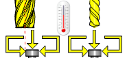
This cycle combines the automatic length measuring cycle and the automatic diameter measuring cycle.
Length and radius values are written into the tool offset register. The wear registers are zeroed and the values are placed in the geometry registers.
Navigation
To access the Thermal Compensation cycle:
- In the CAM Tree, right-click Milling Tools, and select Tool Crib.
The Tool Crib dialog launches in the Data Entry Manager. - Add all tools needed for the job.
- Click OK.
The Tool Crib dialog closes. - In the CAM Tree, locate the desired Machine Setup for the Probing cycle, right-click the Machine Setup, and select Probing.
The Probing dialog launches in the Data Entry Manager. - In the Machining Strategy list of the Feature page, click the Contact Tool Setter operation.
The Contact Tool Setter operation replaces the Measure operation in Current Operations list. - Click the Operations(s) tab.
- Select the appropriate cycle from the drop down list in the Cycle section of the Parameters tab.
The Data Entry Parameters
Parameters
Tool
- Tool Name -
This drop down will list all the tools currently in the tool crib.
- Override Tool Data
 - With this check box selected, you will be able to update the Tool Number and Tool Diameter.
 - With this check box cleared, editing of the Tool Number and Tool Diameter is unavailable.
 - Tool Number - Lists the Tool Number of the currently selected tool.
- Tool Diameter - Lists the diameter of the currently selected tool.
- Base Data Option - determines what the cycle is doing.Choose between:
- Measure and Store - measures the stylus and stores the results to have something to compare to in later cycles.
- Measure and Compare - measures the stylus and compares the results to the initial values stored.
- X Store Location - determines where the X value is stored.
- Y Store Location - determines where the Y value is stored.
- Z Store Location - determines where the Z value is stored.
Options
- Tool Offset - Tool length offset number. This is the offset location in which the measured tool length is stored when it needs to be different from the active tool number.
- Tolerance - When this input is used, the tool offset is not updated if the tool length is found to be out of tolerance.
- Broken Tool Flag - Tool out of tolerance flag. Use this flag to prevent a tool OUT OF TOLERANCE alarm from being raised. Enter the value to be called out with the flag.
- Z Measure Position - This is the Z-axis position from the top face of the stylus at which measurement takes place.
Quick Steps - Thermal Compensation
- In the CAM Tree, right-click Milling Tools, and select Tool Crib.
The Tool Crib dialog launches in the Data Entry Manager. - Add all tools needed for the job.
- Click OK.
The Tool Crib dialog closes. - In the CAM Tree, locate the desired Machine Setup for the Probing cycle, right-click the Machine Setup, and select Probing.
The Probing dialog launches in the Data Entry Manager. - In the Machining Strategy list of the Feature page, click the Contact Tool Setter operation.
The Contact Tool Setter operation replaces the Measure operation in Current Operations list. - Click the Operations(s) tab.
- Select the appropriate cycle from the drop down list in the Cycle section of the Parameters tab.
- In the Parameter section, select the tool and adjust the select the Override Tool Data check box is necessary.
If you select the Override Tool Data check box, adjust the Tool Number and Tool Diameter values as needed. - In the Options section, select the check boxes for any and all calls required in the output and set their values as needed.
- Select the Raw Text tab in order to output any macros or code manually.
- In the Raw Text tab, select the Output in NC Program check box.
- Enter the data to be output in the text field.
- Click OK.
The operation is added to the CAM Tree.
Example 1 - Thermal Compensation - Measure and Store
When using Thermal Compensation the two main steps are to first establish the base values, and later to compare the current values to the base values. In this example we set the base values.
In this example we:
- Setup the Tool Crib
- Select the Thermal Compensation cycle.
- Select the tool.
Part 1) Setting up the Tool Crib
- In the CAM Tree, right-click Milling Tools, and select Tool Crib.
The Tool Crib dialog launches in the Data Entry Manager. - Add all tools needed for the job.
- Click OK.
The Tool Crib dialog closes.
Part 2) Selecting the Thermal Compensation cycle
- In the CAM Tree, locate the desired Machine Setup for the Probing cycle, right-click the Machine Setup, and select Probing.
The Probing dialog launches in the Data Entry Manager. - In the Machining Strategy list of the Feature page, click the Contact Tool Setter operation.
The Contact Tool Setter operation replaces the Measure operation in Current Operations list. - Click the Operations(s) tab.
- By default Automatic Length is the selected cycle.
Click the drop down list and select Thermal Compensation.
Part 3) Selecting the Tool to be set
- In the Parameters section, select the tool to be set from the drop down list.
By default the Tool Offset is set to the tool number of the selected tool. - Click OK to create the Thermal Compensation cycle and exit the dialog.
Example 2 - Thermal Compensation - Measure and Compare
Once the initial base values have been stored, we can call this cycle and compare the current values to the initial values and adjust the work offset as necessary.
In this example we:
- Setup the Tool Crib
- Select the Thermal Compensation cycle.
- Select the tool.
Part 1) Setting up the Tool Crib
- In the CAM Tree, right-click Milling Tools, and select Tool Crib.
The Tool Crib dialog launches in the Data Entry Manager. - Add all tools needed for the job.
- Click OK.
The Tool Crib dialog closes.
Part 2) Selecting the Thermal Compensation cycle
- In the CAM Tree, locate the desired Machine Setup for the Probing cycle, right-click the Machine Setup, and select Probing.
The Probing dialog launches in the Data Entry Manager. - In the Machining Strategy list of the Feature page, click the Contact Tool Setter operation.
The Contact Tool Setter operation replaces the Measure operation in Current Operations list. - Click the Operations(s) tab.
- By default Automatic Length is the selected cycle.
Click the drop down list and select Thermal Compensation.
Part 3) Selecting the Tool to be set
- In the Parameters section, select the tool to be set from the drop down list.
By default the Tool Offset is set to the tool number of the selected tool. - Click OK to create the Thermal Compensation cycle and exit the dialog.