


The 4th Axis Measurement (A Axis) Cycle
Introduction
This topic will explain the 4th Axis Measurement (A Axis) measure cycle, will describe how to access it, will explain the options found in it, and will explain how to use it with quick steps and an example.
The 4th Axis Measurement (A Axis) Cycle
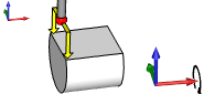
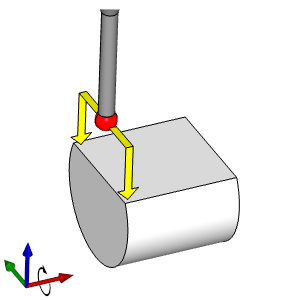
This cycle measures two points along the Y Axis of a planar surface in order to find the angle of the surface along the YZ Plane and make the necessary corrections to the rotary axis to bring the angle to zero and thus ensure a flat surface. This can also be used to check tolerance rather than to correct the rotary axis. This cycle can utilize the following geometry inputs:
- A planar surface whose normal is parallel to the Z Axis.
Note: It is normally necessary on most machines to re-state the work offset
Navigation
To access the 4th Axis Measurement (A Axis) cycle:
- In the CAM Tree, locate the desired Machine Setup for the Probing cycle, right-click the Machine Setup, and select Probing.
The Probing dialog launches in the Data Entry Manager. - Click the Operations(s) tab.
- Click the Parameters tab.
By default the Selected Geometry list is given focus to allow you to select geometry from the graphics area. - Select the applicable geometry.
The geometry is added to the Selected Geometry list and the Initial Position and Parameters section are populated.
Note: Some geometry may be applicable to several cycles. In these cases the cycle that is selected based on the geometry may not be the intended cycle. In these cases, simple choose the correct cycle from the drop down list.
The Data Entry Parameters
Initial Position
-
X - determines the start point for the cycle along the X-axis of the current Work Offset.
-
Y - determines the start point for the cycle along the Y-axis of the current Work Offset.
-
Z - determines the start point for the cycle along the Z-axis of the current Work Offset.
Parameters
-
Z Measure Height - determines the end point for the cycle along the Z-axis of the current Work Offset.
- Width - determines the space between the two touch points along the Y Axis.
-
Update Work Offset
 - Updates the existing work offset values with the information received from the cycle.
 - Does not update the existing work offset.
Options
- K Input
- With this check box cleared, the K value will not be output in the code. - With this check box selected, the K value will be output in the code.
Quick Steps - 4th Axis Measurement (A Axis)
- In the CAM Tree, locate the desired Machine Setup for the Probing cycle, right-click the Machine Setup, and select Probing.
The Probing dialog launches in the Data Entry Manager. - Update the Material Approach and Feature Parameters as necessary.
- Click the Operations(s) tab.
- On the Probe page, select, or define, the Probe to be used.
- Click the Parameters tab.
By default the Selected Geometry list is given focus to allow you to select geometry from the graphics area. - Select the desired piece(s) of geometry.
The geometry is added to the Selected Geometry list and the Initial Position and Parameters section are populated.
Important: The available cycles are filtered by the geometry selected. If you selected geometry and do not have the desired cycle available, remove the geometry and reselect geometry compatible with the cycle.
- Update the Initial Position and Parameters sections as needed.
- Click the Options tab and update any options necessary.
- Click OK.
Example - 4th Axis Measurement (A Axis)
In this example we:
- Set up the UCS.
- Set up the Index System.
- Select the Probe feature.
- Select a probe for the cycle.
- Update the Machining Data and Feed groups.
- Select the cycle.
- Update the cycle.
- Adjust the Initial Position.
- Update the Parameters section.
- Utilize the Options page.
- Backplot the result.
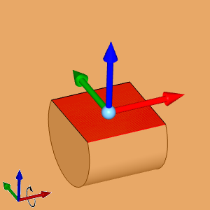
Part 1) Setting up the UCS
When setting up the index system for the 4th Axis cycles, it is important to keep in mind the alignment along the X, and Y Axes. If the part is aligned with these, setting up the index system can be done by simply selecting the surface. However, if the part is not aligned properly, as in this example, it is important to create a UCS system that is aligned properly so the Index System can be created from it.
- In the UCS Manager, right-click and select Add New UCS.
The Create UCS dialog opens in the Data Entry Manager. - At the top of the Create UCS dialog, in the UCS Name text field, type Index System to set the name of the new UCS.
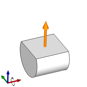
- In the Creation Option group select the Planar Face option.
- In the graphics area select the Planar Face of the part.
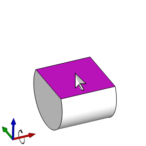
The face is added to the Selected Geometry list, and the UCS preview appears in the graphics area.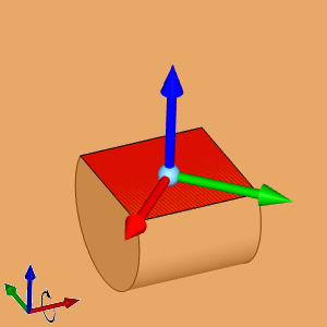
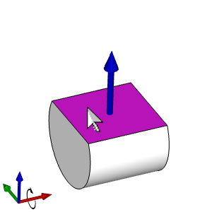
- In the User Coordinate System section, select the Modify check box.
- In the Coordinate System group, click in the list box for X Direction, and click the edge of the part to align the X Axis with.
The UCS updates its alignment.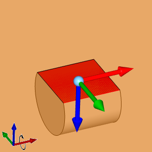
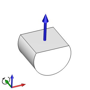
- Next to Z Direction, click the Reverse Direction button to update the direction of the Z Axis.
The Z Axis of the UCS is updated. - Click OK.
The UCS is added to the UCS Manager. - Click Cancel.
The dialog is closed.
Part 2) Setting up the Index System
With our UCS set up properly, we can now use that to align our Index System properly.
- In the CAM Tree, locate the desired Machine Setup for the Probing cycle, right-click the Machine Setup, hover over Addition Functions and select Add Index from the flyout.
The Index System Selection dialog launches in the Data Entry Manager. - At the top of the dialog, select Select UCS.
A drop down list of the current UCS's becomes available, and the index preview is shown based on the currently selected UCS.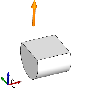
- Select our newly created Index System UCS from the list.
The origin of the index system updates. - Click OK.
The Index System is added to the Machine Setup.
Part 3) Selecting the Probe feature
The first step of any Probing cycle is to create a Probing feature in the Machine Setup it is intended to be used in.
- In the CAM Tree, locate the desired Index System for the Probing cycle, right-click the Index System, and select Probing.
The Probing dialog launches in the Data Entry Manager.
Part 4) Selecting the Probe
Selecting a probe can be done with the following steps, or by simply deselecting the System Tool check box and inputting the appropriate data into the required fields.
- By default Measure is already in the Current Operations list. This will give us access to all available measure cycles in the Operation(s) tab.
At the top of the dialog, click the Operation(s) tab. - By default the Probe page is active. In this page, click the Tool Crib button.
The Tool Crib dialog launches. - Select your probe from the Tool Crib.
- If a probe has not yet been added to your Tool Crib, select the Add From Tool Library button and select one.
- If a probe has not yet been added to your Tool Library, select the
 Add button, define the probe in the Tool Parameters section, and select OK.
The probe is added to the Tool Library and is automatically highlighted. - Click OK.
The probe is updated in the dialog.
- If a probe has not yet been added to your Tool Crib, select the Add From Tool Library button and select one.
Part 5) Updating the Machining Data and Feed groups
When selecting a tool from the Tool Crib, a tool number, and the Height and Diameter Offsets should already be correct. However, if you need to update them, you can do that in the Machining Data group. The Feed group will allow you to set a Protected Feedrate for the probe.
- Update the Machining Data as needed:
- Update the Tool Number if needed.
- To have the cycle update the Height and Diameter Offset, select the Override Offset button and enter the values to update the offsets to.
- Update the Tool Number if needed.
- Update the Protected Feedrate in the Feed group as needed.
Part 6) Selecting the Cycle
The cycle can be selected with the drop down list under the Cycles section, but simply selecting the appropriate geometry will usually select the required cycle automatically. Since certain geometry could be applicable to several cycles, in some cases, the list will become much smaller.
Note: The Pocket measure cycle measures the distance between two parallel surfaces that are both either parallel with the Y Axis, or the X Axis. In this case we measure two surfaces parallel with the Y Axis.
- Click the Parameters tab.
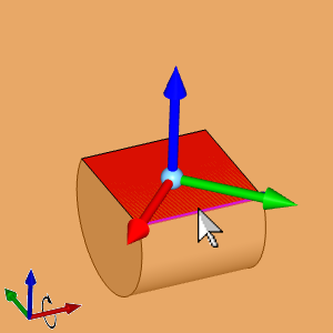
By default the Selected Geometry list is given focus to allow you to select geometry from the graphics area. - Select the planar surface whose normal is parallel with Z.
The geometry is added to the Selected Geometry list, the Initial Position and Parameters section are populated, and the toolpath becomes visible.
Since our current geometry works for a Z Single Surface cycle, that is the cycle that is currently selected for us.
Part 7) Updating the cycle
In this case, the geometry we have chosen could be interpreted as a Z Single Surface cycle.Had we chosen the planar surfaces themselves instead of the edges, the proper cycle would be selected already. However, since we did not, we will need to update the currently selected cycle.
- At the top of the Cycles section click the drop down list and select 4th Axis Measurement (A Axis) from the list.
The toolpath and the available Parameters update.
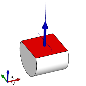
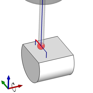
Part 8) Adjusting the Initial Position
There is quite a bit of logic that goes into creating the initial position for you based on the geometry, and the cycle that you choose. While the initial position does not need to be adjusted in this case, we will play with a few of the values to explore how the toolpath reacts.
- In the Initial Position group, update the X value by adding -0.25 to the end, and pressing Tab.

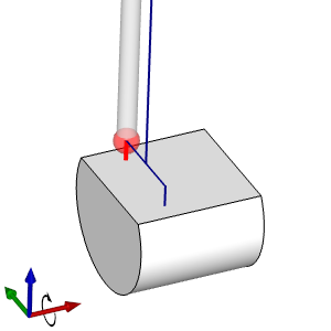
The value and the toolpath update to put the initial position of the probe a half inch further back in X. - In the Initial Position group, update the Y value by adding -0.25 to the end, and pressing Tab.
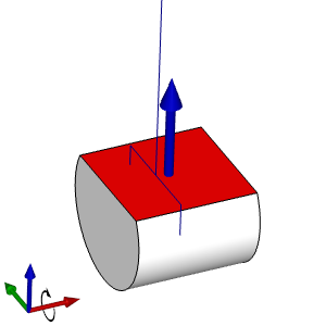
The value and the toolpath update to put the initial position of the probe a quarter inch further back in Y.
However, notice how the end positions are tied to the initial position and one of our contact points is now off of the part. Technically we could correct this by adjusting the Width value in the Parameters section, between the two points, but we will set that value back as it was.
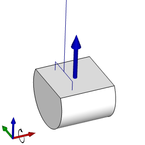
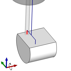
- In the Initial Position group, update the Y value by adding +0.25 to the end, and pressing Tab.
The value and the toolpath update to put the initial position of the probe a half inch further up in Y.
Part 9) Updating the Parameters section
The Parameters section for this cycle consists of the Z Measurement Height, the Width and the Update Work Offset value. In this case we only want to adjust the distance between where the probe will contact the surface. The Update Work Offset value can be used as needed.
- In the Parameters section, update the Width value by adding -0.25 to the value and pressing Tab.

The toolpath width of the contact points is updated.
Part 10) Utilizing the Options page
The values in the Options page should only be utilized if you are familiar with exactly how the individual options work.
- Click the Options tab.
- Update any and all options that are needed for the cycle.
- Click OK to exit the dialog.
The dialog closes and the Probing feature is added to the CAM Tree.
Part 11) Backploting the result
The Backplot is a great way to verify the movements of any of the operations you create.
- In the CAM Tree, right-click the C Measure operation in the Probing feature and click Backplot.
The Backplot dialog launches, and the probe and first move become visible.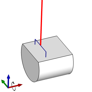
- Click Next three times to view the probe movements.
- Click Close.
The dialog is closed and the feature is ready to post.