


The Thermal Compensation - Radial Cycle
Introduction
This topic will explain the Thermal Compensation - Radial cycle, will describe how to access it, will explain the options found in it, and will explain how to use it with quick steps.
The Thermal Compensation - Radial
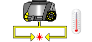
This cycle can be used to calibrate the system for variations in the radial measuring axis caused by temperature changes in the machine tool.
Run this cycle on a regular basis during machining operations to compensate for growth in the radial measuring axis.
This cycle is used as the general calibration cycle, but instead of resetting the calibration data, the beam positions are compared with the original calibration values. The deviation for each axis is then used to adjust the relevant work offset.
Navigation
To access the Broken Tool - Solid Tool cycle:
- In the CAM Tree, right-click Milling Tools, and select Tool Crib.
The Tool Crib dialog launches in the Data Entry Manager. - Add all tools needed for the job.
- Click OK.
The Tool Crib dialog closes. - In the CAM Tree, locate the desired Machine Setup for the Probing cycle, right-click the Machine Setup, and select Probing.
The Probing dialog launches in the Data Entry Manager. - In the Machining Strategy list of the Feature page, click the Non-Contact Tool Setter operation.
The Non-Contact Tool Setter operation replaces the Measure operation in Current Operations list. - Click the Operations(s) tab.
- Select the appropriate cycle from the drop down list in the Cycle section of the Parameters tab.
The Data Entry Parameters
Parameters
Tool
- Tool Name -
This drop down will list all the tools currently in the tool crib.
- Override Tool Data
 - With this check box selected, you will be able to update the Tool Number and Tool Diameter.
 - With this check box cleared, editing of the Tool Number and Tool Diameter is unavailable.
 - Tool Number - Lists the Tool Number of the currently selected tool.
- Tool Diameter - Lists the diameter of the currently selected tool.
- Work Offset - Work offset number used to track axis growth due to temperature effects. This must be the same as that used with the input for calibration.
Options
- Overtravel Distance - The default overtravel distance and radial clearance. Overtravel is the distance through the beam that the tool is permitted to move before a BEAM NOT CUT alarm is initiated. Radial clearance is the distance between the tool and the beam when moving down the side of the beam.
- Spindle Speed - The default spindle speed. Measurement cycles are optimized for a spindle speed of 3000 r/min. Some tools – for example, those that are unbalanced or large – must be run at speeds less than 3000 r/min. This is the responsibility of the user. Use the ‘S’ input to set the speed. Measurement cycle times increase with slower speeds. The minimum speed is 800 r/min.
Quick Steps - Thermal Compensation - Radial
- In the CAM Tree, right-click Milling Tools, and select Tool Crib.
The Tool Crib dialog launches in the Data Entry Manager. - Add all tools needed for the job.
- Click OK.
The Tool Crib dialog closes. - In the CAM Tree, locate the desired Machine Setup for the Probing cycle, right-click the Machine Setup, and select Probing.
The Probing dialog launches in the Data Entry Manager. - In the Machining Strategy list of the Feature page, click the Non-Contact Tool Setter operation.
The Non-Contact Tool Setter operation replaces the Measure operation in Current Operations list. - Click the Operations(s) tab.
- Select the appropriate cycle from the drop down list in the Cycle section of the Parameters tab.
- In the Parameter section, select the tool and adjust the select the Override Tool Data check box is necessary.
If you select the Override Tool Data check box, adjust the Tool Number and Tool Diameter values as needed. - In the Options section, select the check boxes for any and all calls required in the output and set their values as needed.
- Select the Raw Text tab in order to output any macros or code manually.
- In the Raw Text tab, select the Output in NC Program check box.
- Enter the data to be output in the text field.
- Click OK.
The operation is added to the CAM Tree.
Example 1 - Thermal Compensation - Radial
In this example we:
- Setup the Tool Crib.
- Select the Tool Diameter cycle.
- Select the tool.
Part 1) Setting up the Tool Crib
- In the CAM Tree, right-click Milling Tools, and select Tool Crib.
The Tool Crib dialog launches in the Data Entry Manager. - Add all tools needed for the job.
- Click OK.
The Tool Crib dialog closes.
Part 2) Selecting the Thermal Compensation - Radial cycle
- In the CAM Tree, locate the desired Machine Setup for the Probing cycle, right-click the Machine Setup, and select Probing.
The Probing dialog launches in the Data Entry Manager. - In the Machining Strategy list of the Feature page, click the Non-Contact Tool Setter operation.
The Non-Contact Tool Setter operation replaces the Measure operation in Current Operations list. - Click the Operations(s) tab.
By default the Tool Length is the selected cycle.
- Click the drop down and select Thermal Compensation - Radial from the list.
Part 3) Selecting the Tool to be set
- In the Parameters section, select the tool to be set from the drop down list.
By default the Tool Offset is set to the tool number of the selected tool. - Click OK to create the Thermal Compensation - Radial cycle and exit the dialog.
Example 2 - Thermal Compensation - Radial
In this example we:
- Setup the Tool Crib.
- Select the Tool Diameter cycle.
- Select the tool.
- Account for tool deflection with Diameter Experience.
Part 1) Setting up the Tool Crib
- In the CAM Tree, right-click Milling Tools, and select Tool Crib.
The Tool Crib dialog launches in the Data Entry Manager. - Add all tools needed for the job.
- Click OK.
The Tool Crib dialog closes.
Part 2) Selecting the Thermal Compensation - Radial cycle
- In the CAM Tree, locate the desired Machine Setup for the Probing cycle, right-click the Machine Setup, and select Probing.
The Probing dialog launches in the Data Entry Manager. - In the Machining Strategy list of the Feature page, click the Non-Contact Tool Setter operation.
The Non-Contact Tool Setter operation replaces the Measure operation in Current Operations list. - Click the Operations(s) tab.
By default the Tool Length is the selected cycle.
- Click the drop down and select Thermal Compensation - Radial from the list.
Part 3) Selecting the Tool to be set
- In the Parameters section, select the tool to be set from the drop down list.
By default the Diameter Offset is set to the tool number of the selected tool.
Part 4) Accounting for tool deflection with Diameter Experience
- In the Options section, select the check box for Diameter Experience.
- Update the Diameter Experience value to reflect the depth variation found in the probing cycle.
This value will be added to the Diameter found by the tool setter cycle. - Click OK to create the Tool Diameter cycle and exit the dialog.