


BBC File Type
Introduction
This topic explains the .bbcdx file type, provides a use example and links to related topics.
The BBC File Type
The BBC file format allows our users who work with our BobCAD-CAM stand-alone, BobCAM for SOLIDWORKS or BobCAM for Rhino product to share information between the systems. While the geometry information will still be different for each system, you will be able to merge in entire CAM Trees, BobART Trees, and BobART models into the other systems to share as much information as can be between these products. For full functionality, the minimum versions of each product required are as follows:
-
BobCAD-CAM V34 SP0
-
BobCAM for SOLIDWORKS V9 SP1
-
BobCAM for Rhino V1 SP1
Tip: If you save and open bbcdx from BobCAD-CAM they will behave no different than a bbcd file. Opening the .bbcdx file in BobCAM for SOLIDWORKS or BobCAM for Rhino will bring in everything but geometry. If you plan to share bbcdx file between products it is recommended that you create a folder to store the .bbcdx and the shareable geometry file whether it be an .3dm, .iges or other file type.
Warning: When opening a geometry file and then
Navigation
You can access the Save .bbcdx and Load .bbcdx options by selecting Help > BobCAM Help and selecting one of those two options.
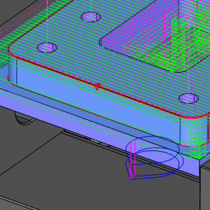
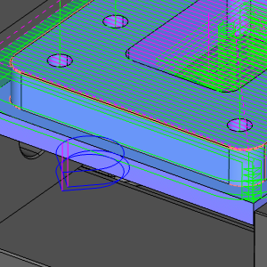
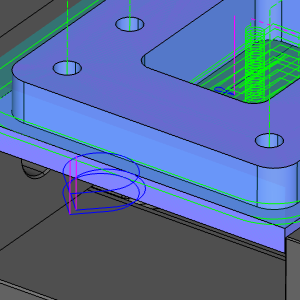
Example Part
The following images show our example part.

The part file for this tutorial is available for download at: http://www.bobcad.com/helpfiles.If you are connected to the Internet, you can click the link providedto download and save the Work Offset Pattern.SLDASM zip file. After extracting the zip file, you can then open the example file to use with this example. In the example file provided, the Tool Crib is already equipped with the necessary tools and the stock and Machine Setup are already defined. The part is simulated using the BC_3x_Mill machine.
Example : Working with BBC
In this example we will explore the functionality of .bbcdx files by saving our file as a .igs file and working with it as if it came from another product.
Part 1) Adding a Mill 3 Axis feature
One of the things this example will help to familiarize you with is the differences between the more basic features, and the Mill 3 Axis, Mill 4 Axis Rotary, and Mill Multiaxis features. Since this example file does not have any 3 Axis, 4 Axis, or Multiaxis features, we will create a basic Mill 3 Axis feature with default settings.
- Right-click
 Machine Setup and click Mill 3 Axis.
The Mill 3 Axis Wizard appears. - In the Mill 3 Axis Wizard, click Select Geometry.
The Mill 3 Axis Wizard disappears and the - Select the check box for Select whole bodies and select the model.
The model is added to the Selected Items list. - Click OK.
The Mill 3 Axis Wizard returns.
In this case we just need generic Mill 3 Axis toolpath, so everything can be left at default. - Click Compute.
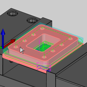
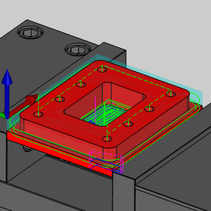
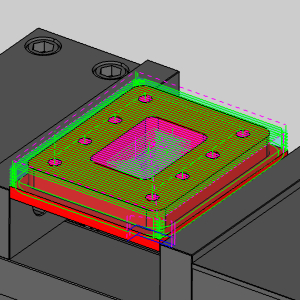
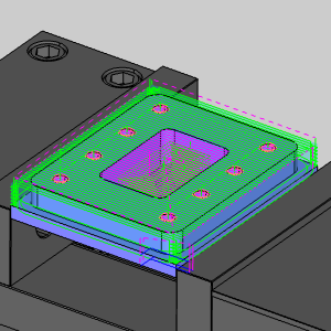
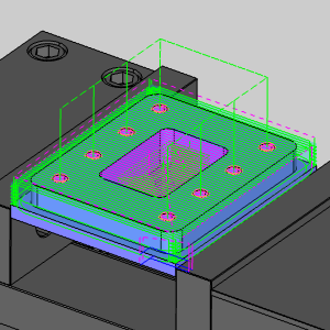
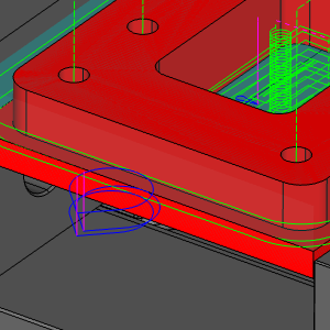
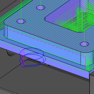
Notice the additional toolpath.
| Before | After |
|
|
Part 2) Saving as .bbcdx and .igs
- With the Work Offset Pattern.
The Save As dialog opens. - Set the file name to Work Offset Pattern.
- Click Save.
The file has now been saved as a .bbcdx file. - To save the geometry file, click File > Save as.
The Save As dialog opens. - Click the drop down next to Save as type: and select .igs.
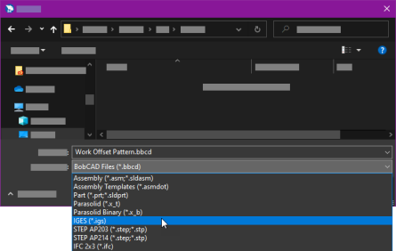
- Click Save.
The geometry file has now been saved. - Close the file.
Part 3) Opening the .igs file
- Click File >
 Open.
Open.
The Open dialog opens. - Update the File Type to .igs.
- Select the Work Offset Pattern.igs file we saved in part 2.
- Click Open.
The geometry is opened and is visible in the graphics area.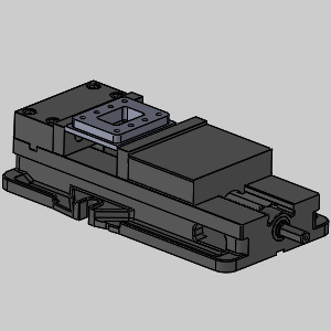
Notice we have no job in the CAM Tree Manager.
Part 4) Loading the .bbcdx
- Click Help > BobCAM Help > Load.bbcdx file.
The Open dialog appears. - Select the Work Offset Pattern.bbcdx file we saved in part 2.
- Click Open.
The Merge Options dialog appears.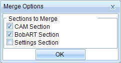
Viewing this dialog from the native BobCAD-CAM software is the only time the CAD options will be available. - Click OK.
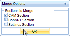
The Merge Options dialog disappears, the CAM Tree Manager opens, and the toolpath is visible in the graphics area.
Part 4) Simulating
- To view the program, in the
 Simulation.
The simulation opens, but an error appears informing us the STL of the fixture cannot be found. - Click OK to close the error.
- To close simulation, in the
 Exit Simulation.
We could simulate by simply removing the fixture geometry from the CAM Tree, but we will take a moment to associate the proper geometry. - In the CAM Tree, right-click
 Fixture, and select Re/Select.
The Fixture dialog appears with focus on the - Select each component of the vise.
- Click
 (OK)
(OK)
The Fixture dialog closes.
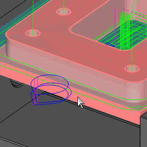
The simulation can now be launched, but while we are assigning proper geometry for the simulation, we will update the Workpiece geometry as well. - Right-click Workpiece, and select Re/Select.
The Workpiece dialog appears with focus on the - Select the part as our Workpiece.
- To view the program, in the Simulation.
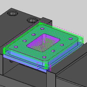
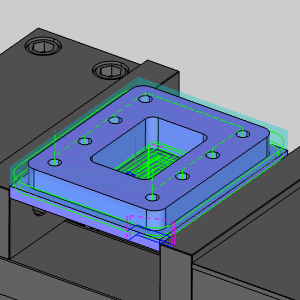
The simulation opens. - Notice that we now have control over the visibility of the stock, fixture, and workpiece.
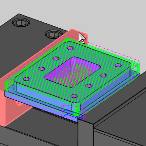
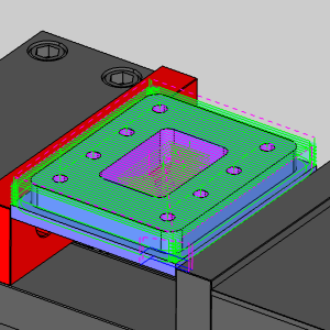
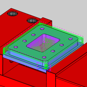
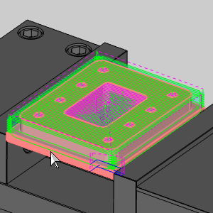
| Stock | Stock and Fixture | Stock, Fixture, and Workpiece |
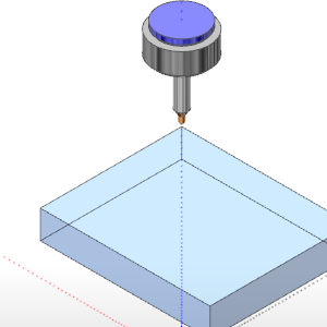
|
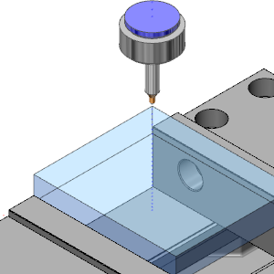
|
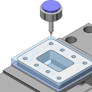
|
Note: When Workpiece geometry is not assigned, all solids are shown as the Workpiece in the simulation.
- To close simulation, in the Exit Simulation.
We could simulate by simply removing the fixture geometry from the CAM Tree, but we will take a moment to associate the proper geometry.
Part 6) Updating Mill Hole features
-
In the CAM Tree, click the Feature Mill Hole - 0.3750 and notice the feature preview highlights in the graphics area.
Right-click and select Edit.
The Mill Hole Wizard launches. -
In the Material Approach group of the Feature page, update the Rapid Plane value to 2.000.
-
Click Compute.
Notice the Rapid Plane has been updated and we have not needed to reselect the feature geometry.
Part 7) Updating Mill 2 Axis features
Section 1) Updating operation parameters
-
In the CAM Tree, click the Feature 2 Axis and notice the feature preview highlights in the graphics area.
Right-click and select Edit.
The Mill 2 Axis Wizard launches. -
In the tree on the left of the wizard, click Leads under Profile Rough.
The Leads page opens. -
In the Lead-in group, select Blend.
-
In the Line section, update the Length value to 0.500.
-
In the Arc section, update the Radius value to 0.500.
-
In the Lead-out group, select the check box for Same As Lead-in.
The Lead-out parameters update to match. -
At the bottom-left of the wizard, click Apply to All Operations.
The lead parameters for the Profile Finish automatically update to match. -
Click Compute.

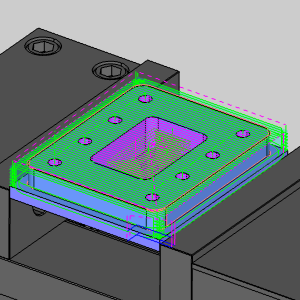
Notice the leads at the bottom right of the part have been updated.
Section 2) Modifying Default Chain Start Point
-
In the CAM Tree, under the same Feature 2 Axis, right-click Default Chain Start Point and select Modify.
The Feature Geometry Picking dialog opens and the chain is highlighted in the graphics area.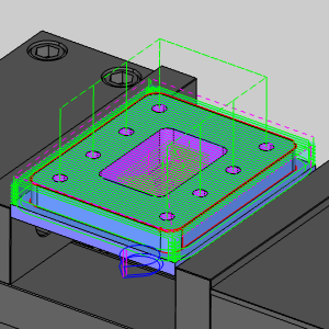
-
In the graphics area, click to the left of the lead near the middle of the part.

The Default Chain Start Point is updated. -
Click OK.
-
Right-click the feature and select Compute All Toolpath.
The toolpath is computed with our leads in the desired location.
Part 8) Updating Mill 3 Axis features
-
In the CAM Tree, right-click Feature 3 Axis and select Edit
The Mill 3 Axis Wizard launches. -
In the tree on the left, select the Patterns under Planar.
The Patterns page opens. -
In the Cut Pattern group, update the Lace Angle to 0.000.
-
Click Compute.
The toolpath disappears.
Any changes requiring you to recompute Mill 3 Axis, Mill 4 Axis Rotary, or Mill Multiaxis features will mean you must associate the proper geometry with the feature. -
Right-click Geometry under the Feature 3 Axis and select Re/Select.
The Feature Geometry Picking dialog opens with focus on the Selected Geometry list. -
Select the Select Solid Body check box above the Selected Geometry list.
-
Select the model.
-
Click OK.
The Feature Geometry Picking dialog closes. -
Right-click the Feature 3 Axis and select Compute All Toolpath.
The Planar toolpath now moves parallel to the X Axis.
That concludes this example.
Related Topics
The Stock Wizard and Machine Setup Tutorials
Next Topic
Click here to go to The Milling Job topic.
Click here to go to The Mill Turn Job topic.
Click here to go to The Wire EDM Job topic.