


Emboss Swept Example 1
Introduction
This help topic provides a basic example to help you get started creating Emboss Swept features. By providing the fundamental information about this feature type, this topic can be useful for beginners or advanced users alike.
For this example, you start from a new file. The entire process of creating an Emboss feature is explained.
Important Notes
- There are two geometry items used: the feature geometry and the cross section.
- The feature geometry defines the path of the sweep (in X and Y).
- The cross section defines the shape of the emboss (in Z) that is swept along the feature geometry.
- The feature geometry can be either open or closed geometry chains.
- One or more chains can be selected for a single feature.
Example
Part 1) Create Geometry
The Emboss Swept feature geometry can be any combination of open or closed chains. The entities used for the chains can be any combination of lines, arcs, and splines.
- In the File menu, click New.
- With the Part option selected, click OK.
The new part opens with the Feature Manager Design Tree open. - Ensure the document is set to inches.
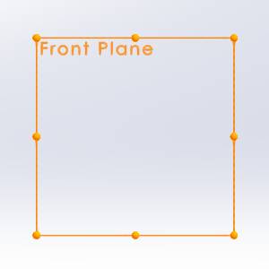
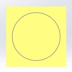
- Click Front Plane, and select Sketch.
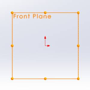
The Sketch ribbon becomes available. - Select the Circle function.
The function opens in the Property Manager
entity, and - Move your mouse to the origin.

- With the point visible, click the origin.
- Move your mouse up until a value of 2 is reached, and click again.
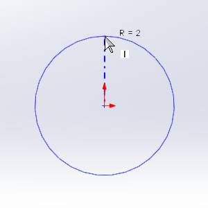
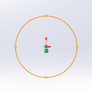
- Click Exit Sketch.
Part 2) Create the Canvas
-
In the
 BobART Manager, right-click
 Emboss Model,and click Edit Canvas.
 -
By default the UCS is set to
-
In the Canvas Definition dialog, in the Origingroup, double-click (click twice quickly) in the Xfield so that the entire value is selected. Type
-
In the Yfield, type
The Origin settings define the lower-left corner (origin) of the canvas in the graphics area. The Origin values set the distance from the WCS or world coordinate system. This is also known as the CAD coordinate system.
 -
In the Canvas Size group, set the Xvalue to
These values represent the length of the canvas along each of the X-and Y-axes. -
To set the color of the canvas, click the drop down next to Canvas Color and select one of the colors.
-
Click OK to create the canvas.
Notice the location of the canvas origin (lower-left corner). Also note that the geometry created earlier is contained within the bounds of the canvas. -
To close the dialog, click Cancel.
Note: The canvas for embossed models is created with zero thickness.
Part 3) Add the Feature and set Attributes
-
In the
BobART Manager, right-click Emboss Model, and click Emboss Swept. -
In the Attribute section of the Emboss dialog, click in front of the existing text in the Name field and type My so the text reads My Emboss Swept 1.
-
To define the color of the feature, the drop down next to Color and select one of the colors.
-
Confirm the Application Type is set to Add.
Part 4) Select Geometry
-
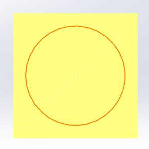
By default the Selected Geometry list has focus, so In the graphics area, select the arc we created earlier.
Part 5) Setting the Cross-Section
-
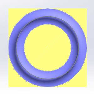
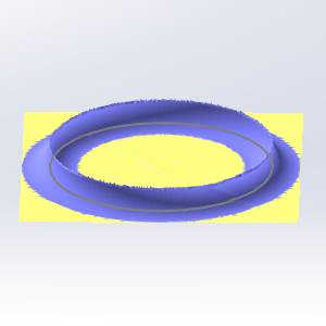
In the Cross-Section section, confirm that Convex Arcis selected.
-
In the Radiusfield, type . Notice that the cross section preview is updated in the dialog box.
All of the other settings remain at the default values. -
To update the canvas, click Apply.
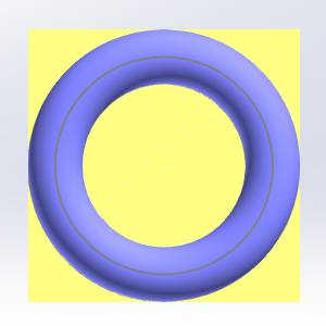
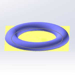
Note: Notice that the cross section, defined in the Emboss dialog, is swept along the entire length of the feature geometry. The cross section defines the shape of the emboss vertically in Z. The Application Type, Add, means that the feature is added (or raised) in the positive Z-axis. The Z-height of the feature is because of the radius (Convex Arc) cross section used.
Part 6) Edit the Feature
This next section could have been done before exiting the dialog, however for this example we exited to show how to edit a feature from the BobArt Tree. To edit the feature, you use the Emboss Feature in the BobART Tree.
-
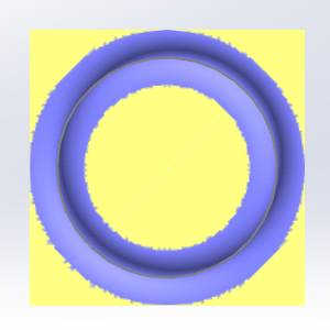
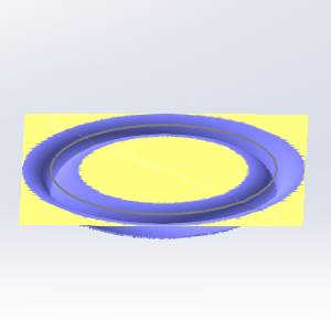
In the Cross-Section section of the Embossdialog, click the drop down currently showing the Convex Arc option and select Concave Arc instead.
-
To update the model and show the result of the new setting, click Apply.
Again, the defined cross section is swept along both sides of the selected feature geometry. -
In the Attributesection of the Emboss dialog, update the Application Type to Subtract.
This means that the feature is lowered in the negative Z-axis direction. -
Click OK to regenerate the model and exit the dialog.
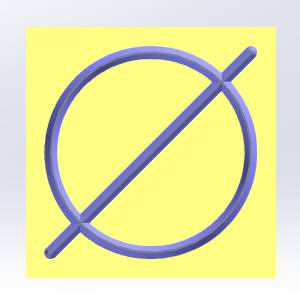
Part 7) Create a Line
- Right-click the sketch in the Feature Manager Design Tree, and select Edit Sketch.
- Select the Line function.
- Hover over the bottom corner of the circle.
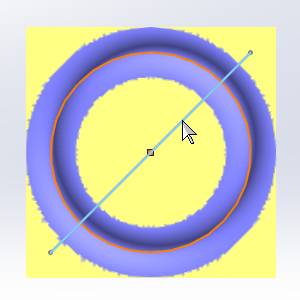
With the construction lines are visible, click your mouse and move to the top right of the circle.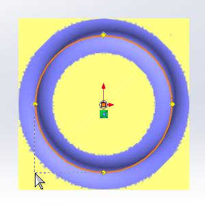
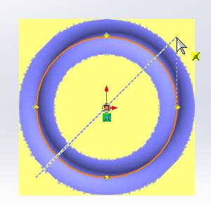
- With the construction line visible, as seen in the above image, click again to create the line.

- Move your mouse and double-click to end the line function.
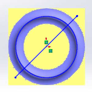
- Click Exit Sketch.
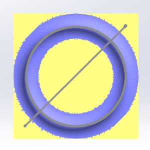
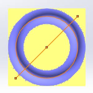
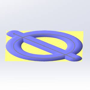
Part 8) Select Multiple Chains for a Single Feature
You can select multiple chains for a single Emboss Swept feature. The process of sweeping the cross section along the chain to create the emboss is applied to each chain regardless of how many chains are selected.
Tip: In the BobART tree, click ![]() My Emboss Swept 1 - Subtract. Notice that the feature geometry is highlighted in the graphics area. You can use this preview to locate each feature when the BobART tree contains multiple features.
My Emboss Swept 1 - Subtract. Notice that the feature geometry is highlighted in the graphics area. You can use this preview to locate each feature when the BobART tree contains multiple features.
-
In the
BobART Manager, right-click  Geometry, and click Re/Select.
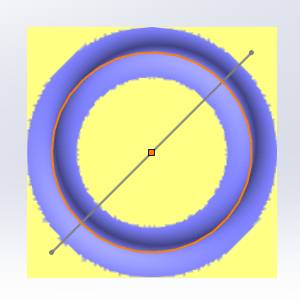
The Emboss dialog opens again and the previous feature geometry is still highlighted. This shows that it is still selected. -
In the graphics area, click the line to select it.
-
Set the Application Typeback to Add.
-
Set the Cross Section back to Convex Arc.
-
Click Apply.
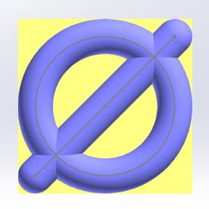
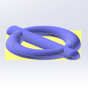
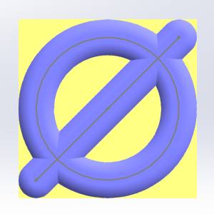
Note: When combining multiple emboss features, the Add application type adds the results of each feature together. In the previous images, because the two separate chains were selected for a single Emboss Swept feature, they are created at the same height (). The following images show the result of creating two Emboss Swept features and assigning the arc to one feature and assigning the line to the other feature.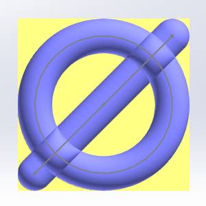
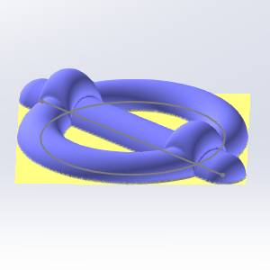
The result is that the intersecting areas of the two features are added together. The arc used for each feature results in the total Z-height of the model of .00.
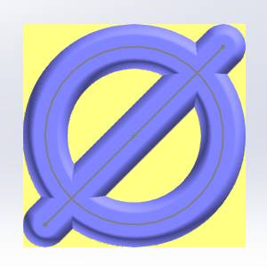
Part 9) Modifying the Cross Section
When using the cross-section types, Convex Arc or Concave Arc, you can modify the cross section using the Start Angle and End Angle parameters.
-
In the Cross Section section, set the Start Angleto 45.00.
This causes the cross section to start at the midpoint of the arc (45 is half of 90). The range of possible values for the Start Angle and End Angle are from 0.00 to 90.00 degrees. -
Click Apply.
Note: The Z-height of the model is now much lower than the previous result.
Part 10) Modify the Cross Section in the Emboss Dialog Box
When using any of the standard cross-section types in the Embossdialog box, you can manually edit the cross section using the cross section preview that is displayed in the dialog box.
-
In the Cross-Section section of the Emboss dialog, click the drop down currently showing the Convex Arc option and select Line instead.
-
In the preview, click the red point on the right side. Drag (click and hold the mouse button) the point left to the vertical 0.125 grid line as shown next.


-
Notice that the parameters of the line are updated in the Cross Section group.
-
Click Apply.

Part 11) Using Fast Edit
The Fast Edit section of the Emboss dialog box is used to scale the cross section or to add a base height which creates a wall at the bottom of the feature.
-
To better show the results of using the Fast Edit section, set the Cross Section to Convex Arc, and set the Radiusto .
-
Set the StartAngle to 0.00.
-
Regenerate the feature by clicking Apply.
The model should appear as it did earlier in this example. -
In the Fast Edit section, set the Base Heightto 1.00.
-
Click Apply.
-
In the FastEdit group, set the X-Y Scaleto 0.500, and set the Z Scale to 1.500.
These settings cause the defined cross section to be 50 percent of the size in the X- and Y-axes and 150 percent of the size in the Z-axis. -
Click OK to show the results and exit the dialog.
Note: When using the X-Y Scale and Z Scale parameters, only the Cross Section is scaled. The scaling does not affect the Base Height or the feature geometry.
Part 12) Define a Custom Cross Section
In addition to using the standard cross-section types that are available in the Emboss dialog box, you can also define a custom cross section using geometry that you create in the graphics area.
To learn more, view How to Use a Custom Cross Section.
This concludes the example.