


Emboss from Component Example 1
Introduction
This help topic explains how to create an Emboss from Component feature using BobART. In this example, you work with an existing part which is an artistic sign. The base of the sign, including a texture, is complete. Multiple Emboss from Component features are added to the model using the same component for each feature. The component features added in this tutorial are used to complete the design of the part.
Example File
If you are connected to the Internet, the part file for this example can be downloaded automatically by clicking the following link: Emboss fromComponent Example 1.sldprt
Once you download and saved the zip file, extract the files on your system in an easy place to remember.You can then open the file to use with this tutorial. All files for the tutorials in this help system available for download can be found by clicking on the following link: http://www.bobcad.com/helpfiles.
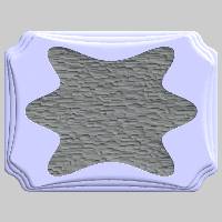
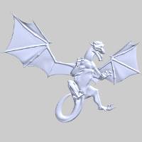
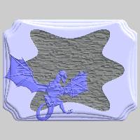
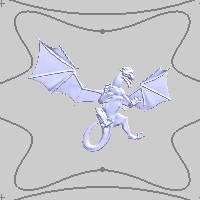
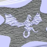
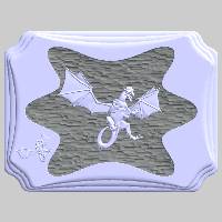
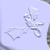
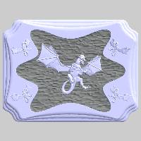
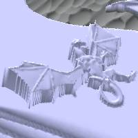
In the example file provided, a few emboss features are already created to make an artistic sign as shown in the following image. The component (.stl file) used in this tutorial is shown in the second image.
Part 1) Open the Example File
- After downloading the zip file and extracting the files to your system, click File > Open.
-
In the Opendialog, navigate to the location in which you saved the example file.
-
Select Emboss from Component Example 1.
-
In the
 BobART Manager, next to
  Emboss Model, click
  to expand the tree.
You see the four previously defined Emboss features in the tree.
Part 2) Add the First Emboss from Component Feature
The component used in this tutorial can be downloaded using the Example Files link at the beginning of this help topic. If you have already downloaded the example files and you have completed the Emboss from Image example, you can use the component you created in that tutorial.
-
In the BobARTtree, right-click
Emboss Model, and click Emboss from Component.
The Emboss from Component dialog is displayed. -
Click the Load Component File button.
-
In the Opendialog, navigate to and select the folder in which you have saved the component.
-
Select Dragon Component.stl, and click Open.
The component appears in the emboss. -
Notice that the component is automatically placed with the origin (lower-left corner) of the component at X0Y0Z0.
-
Click the Blank Emboss button at the top-right of the dialog.
-
Click Blank Emboss once more to show the emboss again.
-
Before defining the feature parameters, clickOK to generate the feature as is.
(Normally you define the parameters first, but for this example, this is done to show you what to expect when editing the feature.) -
To edit an emboss feature, you use the Emboss Feature in the BobART Tree.
In the BobARTtree, right-click ![]() Emboss from Component
Emboss from Component
Part 3) How to Use the Emboss from Component dialog
-
Click Blank Emboss.
-
In the Attribute group, click Color.
In the Color dialog, select More Colors..., set the values to R204, G204, B255and click OK.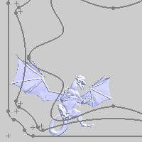
-
To update the size of the component to better fit the model, in the Canvas Sizegroup, change the X Size value to 12.000 and press Tab.
Notice that the Y Size and the Z Height values are automatically updated because the Keep Same Ratio check box is selected.
The preview of the component is updated.(The preview continues to show the current appearance of the component, and it also shows any modifications of the component being edited.) -
In the Origingroup, set the X value to5.00, and set the Yvalue to5.00.
You can see that the component still needs to be adjusted some to be centered in the textured area. -
In the Origingroup, next to X, click the up arrow until the model appears in the proper location (in X).(The final value for this example is X
-
Repeat this process for the Yvalue of the component. Click the arrows until the component appears in the desired location.(For this example, the final value is Y
-
Unblank the emboss and click Apply.

Notice that the texture is being applied to the component. This is a result of the application type, Add, and the location of the feature.(The component is being added to the Emboss Texture feature.)
Part 4) Edit the Application Type
-
In the Origingroup, set the Z value to 0.550.
This setting is used to move the component up (in the positive Z-axis direction) so that the Merge High application type can be used. -
In the Application Type group, click the arrow, and click Merge High.
This eliminates the texture from appearing in the component feature because only the highest portion of the model is kept. -
To update the changes in the model, click Apply.
Part 5) Add the Second Component
When creating Emboss from Component features, you can add as many features as you need using the same component. This means you don't need to have multiple copies of the same component in order to create multiple features from the same component.
-
Right-click
Emboss Model, and click Emboss from Component. -
Click Load Component File.
-
In the Opendialog, select Dragon Component.stl,and click Open
-
In the Size group, change the X Sizevalue to 4.00 and press Tab.
-
Under Orientation,in the Rotation group, set the Z value to 45.00.(This rotates the component around the Z-axis.)
-
Update the Application Type to Add.
-
In the Origingroup, set the X value to 1.250, and set the Yvalue to 3.400.
You can click the Blank Emboss button at the top right of the dialog to hide the emboss and better see the placement of the new component.
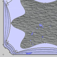
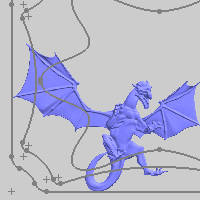
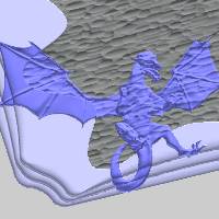
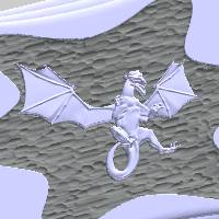
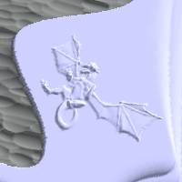
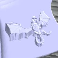
Important: When placing components in the Emboss from Component dialog, the origin is found by creating a bounding box around the component. The lower-left corner of the bounding box is the origin (as shown in the following image). When you rotate components in the Emboss from Component dialog, the origin is automatically updated to remain at the lower-left corner of the component's bounding box (as shown in the second image).

-
To accept the parameters and close the dialog, click OK.
Part 6) Add the Third Component
-
Right-click
Emboss Model, and click Emboss from Component. -
Click Load Component File.
-
In the Opendialog, double-click to select and open DragonComponent.stl.
-
In the Canvas Size group, change the X Sizevalue to 4.00.
-
Under Orientation,in the Rotation group, set the Z value to -45.00.
-
In the Mirrorgroup, select the
Y-Z Plane check box. -
In the Origingroup, set the X value to 18.700, and set the Yvalue to 3.400.
-
To regenerate and close the dialog, click OK.
Part 7) Add the Fourth Component
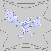
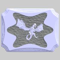
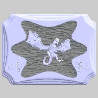
You can continue to add components to create mirrored patterns as shown next.
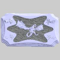
In the next few parts of the tutorial, you add the final two components as shown in the previous images. This time rotation is also applied in the X- and Y-axes to make the dragon protrude from the sign.
-
Right-click
Emboss Model, and click Emboss from Component. -
Click Load Component File.
-
In the Opendialog, select Dragon Component.stl,and click Open.
-
In the Emboss from Component dialog, make the following settings.
In the Canvas Size group, change the X Size value to 4.000.
In the Rotation group, set the X value to 12.250.
In the Origin group, set theX value to 1.250, and set the Y value to 11.600.
Click OK.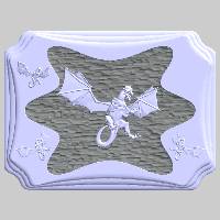
-
Right-click Emboss from Component 8, and click Edit.
-
In the Rotationgroup, change the Xvalue to 0.00.
In the Y box, type 12.250.
Click OK.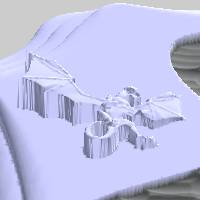
-
Edit the feature (as in Step 4), and change the following parameters.
In the Rotation group, change the Xvalue to 12.250.
In the Z box, type 45.00.
Click OK.
Part 8) Add the Fifth Component
-
Right-click
Emboss Model, and click Emboss from Component. -
Click Load Component File.
-
In the Opendialog, double-click to select and open DragonComponent.stl.
-
In the Canvas Size group, change the X Sizevalue to 4.000.
-
In the Rotationgroup, set the X value to 12.250, and set the Y value to -12.250.
Set the Z value to -45.00. -
In the Mirrorgroup, select the
Y-Z Plane check box. -
In the Origingroup, set the X value to 18.700, and set the Y value to 11.600.
-
Click OK.
This concludes the tutorial.