


How to Vectorize Using the Multi-Color Strategy
Introduction
This topic explains how to vectorize an image using BobART.The use of the Multi-Color Strategy is the main focus, but the Black and White strategy is also examined.Many useful tips and a few different approaches are provided.
Example File
If you are connected to the Internet, the part file for this example can be downloaded automatically by clicking the following link: Image Vectorization Example 1.sldprt
Once you download and saved the zip file, extract the files on your system in an easy place to remember.You can then open the file to use with this tutorial.All files for the tutorials in this help system available for download can be found by clicking on the following link: http://www.bobcad.com/helpfiles.
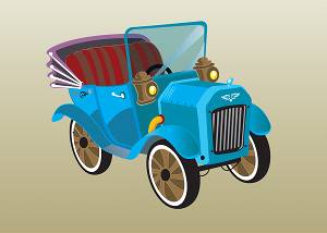
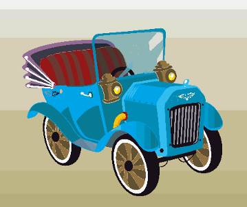
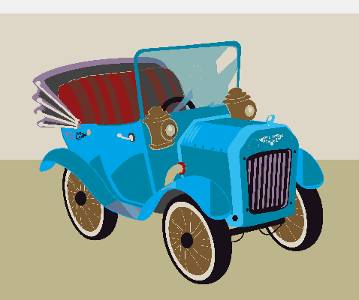
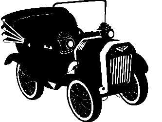
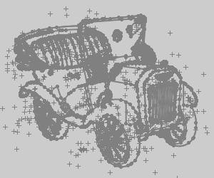
In this example, a color image of a car is used to create vector geometry.The image used is shown next.
This tutorials explains the following BobART functionality:
-
Loading an image using the BobART Manager
-
Selecting the image location
-
Hiding and showing images
-
Moving and scaling images
-
Using the Vectorize... dialog to vectorize an image
-
The 2-level black and white strategy
-
The multi-color strategy
-
-
Using Remove Chains Less Than
-
Editing the vectorization parameters
-
Exploring workflow methods and many helpful tips
Part 1) Open the Example File
-
Click File > Open.
The Open dialog is displayed. -
In the Opendialog, select the folder in which you saved the example files.
-
Select Multi-Color Vectorization Example 1.
The file is opened (the graphics area is empty). -
Click the
 BobART tab to access the BobArt Tree.
Part 2) Load the Image, Select Location, Size and Transparency
Note: For this example, we are simply vectorizing an image without using other geometry, so we can focus on the process of vectorizing the image.You may want to move or scale an image in order to use the resulting geometry with an existing model.This section shows you how to do so.You can use these steps before or after vectorizing an image, depending on how you prefer to work.
Loading the image
-
In the BobARTtree, right-click
 Images, and click Load Image.
 -
Select the Front Plane from the Feature Manager design tree and click
 .
.
We are selecting the Front Plane, so the vectorization result is placed in a 2Dsketch.If we didn't make a selection, the vectorization result would be placed in a 3Dsketch.
Either way the resulting geometry is the same, but working with the sketch feature in SolidWorks is slightly different. -
In the Opendialog, select the folder in which you saved the example files.
-
At the bottom of the dialog, next to Files of Type, click the arrow and select All Files (at the bottom of the list).
You can also go through the list to find the specific file type you need. -
Select Old Car.bmp, and click Open.
The image is loaded and displayed in the graphics area.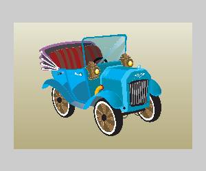
Notice the Image-Old Car item is added to the BobART tree under Images.
Selecting a location
-
In the BobArt Tree, right-click the
Image-Old Car item, and select Edit.
The Sketch Picture dialog opens in the Property Manager.
-
The bottom left of the image is placed at the Origin position.
This can be adjusted by editing the values in the fields, or by placing your mouse over the image and dragging it into the desired position.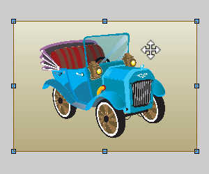
For this example, we leave the origin at 0 for all values. -
If needed we can add a rotation angle to the image, but keeping the edges parallel with the X and Y axis is the desired result in this case, so this value is left to 0 as well.
Setting the size
-
The current size of the image is listed as:
-
Width = 11.9567
-
Height = 8.5300
-
-
These values can be updated by adjusting the values in the fields directly, or by using your mouse in the graphics area to pull the given points in the desired direction.
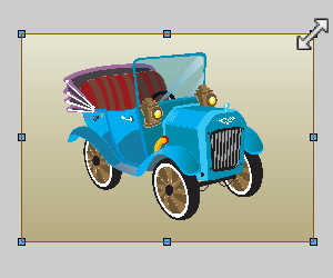
In this case we will leave the size as it is, but adjusting one of these values with either method automatically adjusts the other to keep the aspect ration of the image.To adjust a single value independently, clear the
Setting the Transparency
-
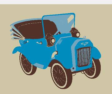
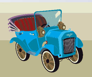
To adjust the transparency, in the Transparency group at the bottom of the dialog, select Full Image and either adjust the slider, or set the value between 0 and 1.
In the images below you will see the a value of 0, followed by a value of 0.75.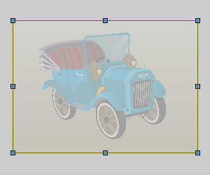
In this case we will leave the Transparency at 0. -
Ensure the Transparency is set to 0, and click OK.
Tip: When modifying the image this way, any previous vectorization result remains in the previous location.To update the results to the new location, you can simply open the Vectorize... dialog and click OK.Alternatively, you can use any standard CAD functionality to move or modify the vectorized geometry.Any vectorization performed after moving the geometry, automatically uses the new location.
Warning: Making changes to the image in the dialog affects them permanently.If you adjust the size for instance, canceling the dialog does not reset the image to the original size.If you forget what the original size was, you would need to delete the image and reload.
Part 3) Hiding and Showing the Image
When vectorizing images, you need to hide and show the image in order to view and work with the geometry that is created.There are two ways to hide images, and it is important to understand how they work.
-
In the Quick Access Menu at the top of the BobART tab, click the
 icon.
icon.
All images in the graphics area are hidden.
Repeat the process and all images are shown. -
Right-click on
Images and select Blank/Unblank All.
All images in the graphics area are hidden.
Repeat the process and all images are shown. -
Right-click
 Image-Old Car, and click Blank/Unblank.
The image is hidden.This method is used to hide or show a single image.
Repeat the process to show the image.
Note: For this example, you can use either method to hide and show the image, since we only have a single image.Notice when hiding the image, the blanked icon ![]() displays next to the image icon in the BobART tree.
displays next to the image icon in the BobART tree.
Part 4) Using the Vectorize... dialog
This section explains how the Vectorize... dialog is used to create and modify the vectorized geometry.
The Multi-Color Strategy
In this section we begin using the multi-color strategy to vectorize the image and begin exploring the various workflow options for creating and saving geometry.
-
In the BobARTtree, right-click
Image-Old Car, and click Vectorize.
The Vector... dialog is displayed. -
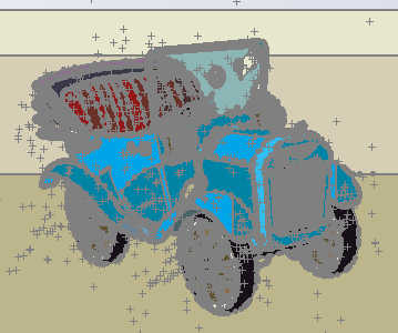
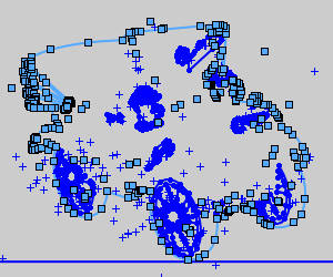
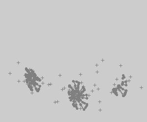
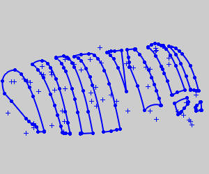
In the Method group of the Strategy section, click Multi-Color Strategy.
The image is shown divided into 64 specific colors.The multi-color strategy defaults the number of colors to 64, which allows you to target very specific colors or color ranges in the image in order to be more precise with the vectorization results.Experimentation with the number of colors is an important aspect of learning to vectorize images in an efficient manner. -
Next to # of Colors, click the down arrow and select 64.
-
At the bottom of the Parameters group, under the color boxes, click Check All.
-
Click Apply to vectorize the image in its current state.
-
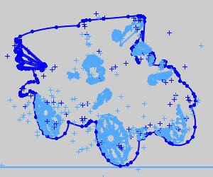
Next to # of Colors, click the down arrow and select 32.Notice the change in the preview.For example, the gradient of the image background is reduced from 6 unique colors to 5, and the yellow and orange colors are removed from the head lights and the exhaust.
When you change the number of colors, the image is actually reduced to the selected number of colors, and the color boxes update under Colors to be Vectorized.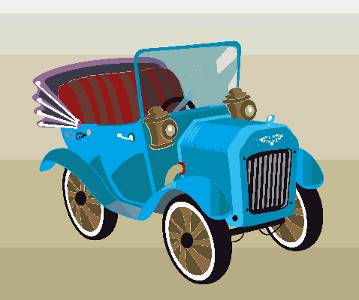
-
Continue reducing the # of Colors (for example to 16, 8, and 4), and observe the change in the preview.

-
Change the # of Colors to 24 and click Check All to automatically select the check box of all colors.
-
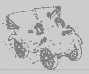
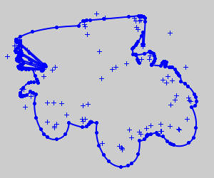
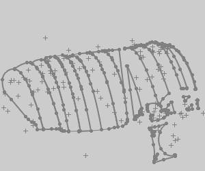
Click OK to vectorize the image.
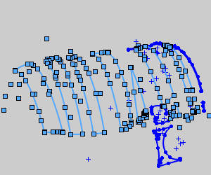
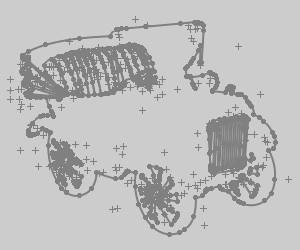
The image is processed using all 24 colors to create the vectorized geometry.Notice the horizontal lines.This is a result of the gradient in the background of the image.The current settings separated the gradient into three unique colors.
Although it is not the method used for this tutorial, you could decide that you are now done with the vectorization and simply edit the geometry.Depending on what you want to achieve, this may not be the most efficient method to use.When using this method, you are vectorizing many adjacent colors, which results in a large amount of entities.Regardless of how you choose to work, we explore another important parameter next, Remove Chains Less Than.
Remove Chains Less Than
-
Next to
Image-Old Car, click  to expand the tree item.
To edit the parameters, right-click Vectorization, and click Edit.
Note: You can also right-click Image-Old Car, and click Vectorize.
-
In the Vectorize... dialog, set the # of Colors to 64.
-
Click Uncheck All.
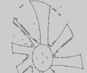
-
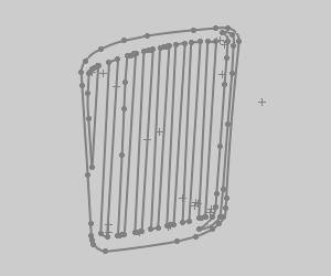
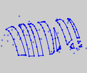
Select the colors seen in the image below.

-
Click the
Blank Image button at the top-right to hide the image so we can better view the results. -
Select the Create in New Sketch option.
-
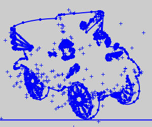
Click OK.
Notice that the geometry from the first vectorization is removed and replaced with new geometry.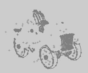
When there is geometry that you want to keep, you
Part 5) Update the Sketch
-
-
With the desired entities selected, zoom out in order to see everything, hold Ctrl and window-pick all entities to invert the selection.
-
With everything but the desired entities selected, press Delete on your keyboard.
-
Exit the new sketch.
-
Update the sketch name to Grill.
-
Hide the sketch.
Part 6) Use the Black and White Strategy
The 2 Level Black and White Strategy
This section explains how the Vectorize... dialog is used to create and modify the vectorized geometry.We start by experimenting with the 2 Level Black and White strategy, as it is a viable option for vectorizing color images or black and white images.The strategy simply determine show the image is analyzed in order to create geometry.
-
In the BobARTtree, right-click
Image-Old Car, and click Vectorize.
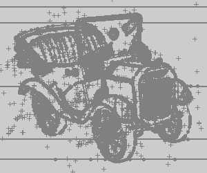
The Vectorize dialog displays and the image appears in blank and white with only portions visible.
This is because in the Strategy section, the Method is set to 2 Level (Black/White) Strategy by default. -
In the Threshold Value field, update the value to 40.
No noticeable change occurs. -
Update the value again, but this time, use 60.
Notice the preview of the image updates each time that you change the value.
You can also click and drag the Threshold Value slider, in small increments, and release (to accomplish the same task). -
Change the Threshold Valueto 140.
-
Make sure the Create in New Sketch option is cleared.
-
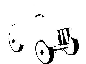
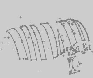
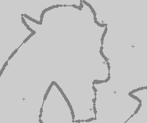
Click OK to vectorize the image
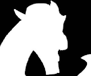
Hide the image to view the geometry.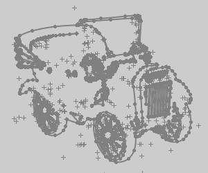
The resulting geometry is -
To edit the vectorization we did, either:
-
Right-click
Image-Old Car, and click Vectorize... to enter the dialog again. -
Under
Image-Old Car, right-click Vectorization, and click Edit.
The Vectorization item was added to the BobART tree after the first vectorization.
-
-
Clear the Create in New Sketch check box since we intend to edit our created geometry and not create additional geometry.
This step is only shown to illustrate a point and is not recommended when using choice geometry from multiple vectorizations to produce the final result. -
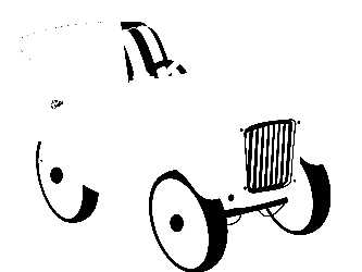
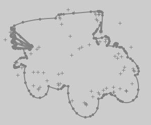
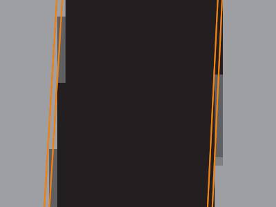
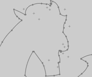
Change the Threshold Value to 174 and clickOK to update the vectorization result.
Notice that the geometry from the first vectorization is removed and replaced with new geometry
Tip: This is where the Create in New Sketch option becomes important.Currently we cannot hide the resulting geometry on the original sketch without hiding the image itself.Hiding the sketch through the Feature Manager Design Tree automatically hides the related image which can then not be shown through the BobART Tree.To avoid loading multiple copies of the same image in the Feature Manager Design Tree, we edit the original sketch, delete the geometry we have just created, exit the sketch, and redo the last vectorization using the Create in New Sketch option.
For this part, you experiment with the Black and White strategy to get the profile of the car.
-
In the Feature Manager Design Tree, right-click the new sketch and select Edit Sketch.
-
Right-click an entity in the outer profile and select Select Chain.
-
Zoom out, hold Ctrl and window pick all entities.
Selection is inverted. -
Click Delete.
-
Exit the sketch and update the name to Profile.
Part 7) Continue Using the Multi-Color Strategy
-
Right-click
Vectorization, and click Edit. -
Select Multi-Color Strategy.
-
Click the # of Colors arrow, and click 32.
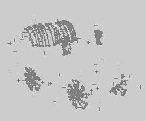
Notice that the preview of the image changes based on the # of Colors selected.
When you change the number of colors, the image is actually reduced to the selected number of colors, and the color check boxes are also updated under Colors to be Vectorized.
Repeat this process of reducing the # of Colors (for example to 16, then 8, then 4, etc.) and observing the image preview.
This process is very helpful when trying to vectorize only a certain area of the image. -
Set the # of Colors to 24.
Click Uncheck All.
Click to select the top check box in column 2 of Colors to be Vectorized.
Click OK.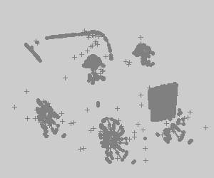
-
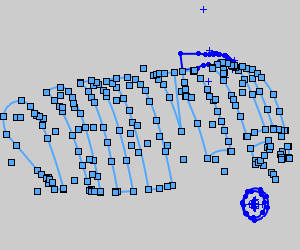
When you zoom-in to view the front wheel, you can see that there are small unwanted entities as shown next.
Part 8) Remove Chains Less Than
Remove Chains Less Than
The Remove Chains Less Than parameter is very important when vectorizing images, as it helps you to remove unnecessary geometry that may be created from the gradients in an image.
-
Show the image, and zoom-in closely to different areas of the image and notice the geometry as compared to the selected colors (gradients).For example, the grill on the front of the car or the wheels are a great place to view how the geometry is created based on the colors.
The following image shows the colors of the front grill zoomed in closely with the geometry hidden from view.You can see that there are actually three colors that make the vertical black and gray stripes.
Because we have vectorized all 24 colors, the software created geometry for each color.The first point here is that you may not want to vectorize adjacent colors, as it results in what appears as duplicate geometry, although it isn't.It may be better to vectorize only one of the colors.The second point is that the darker gray color results in very small entities that are most likely not needed.The geometry from our vectorization is shown next highlighted to make it easier to view.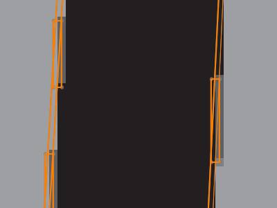
You can see the small rectangles are not needed, so now we use the Remove Chains Less Than parameters to remove them. -
Delete the last sketch.
-
Right-click Vectorization,and click Edit.
-
Under Vectorize Parameters, change the Remove Chains Less Than value to 75(pixels), and click OK.
You can see that the small groups of entities are now removed from the result.You can experiment with the Remove Chains Less Than value to make the vectorization result more efficient.Next we explore more ways to be efficient with vectorization.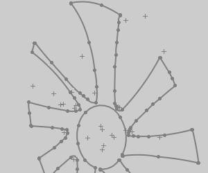
-
Edit the sketch.
-
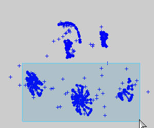
In the graphics area, window-pick the three wheels as shown next.
-
Hold Ctrl and window-pick everything to invert the selection.
-
Click Delete and exit the sketch.
Note: To get the other contours from the wheel, the following color is used.
The Remove Chains Less Than value was changed to 100, to create the following result.
Be sure to reduce the Remove Chains Less Than value(if needed) when moving on to vectorize a new area of the image.
Part 9) Edit the Vectorization Parameters
In this part, the seat is the target area from which you create geometry.
-
Right-click Vectorization,and click Edit.
-
Change the # of Colors to 20.
-
Select the following colors.

-
In the Remove Chains Less Thanbox, type 100.
-
Click OK.

The result appears as though some of the geometry is missing from these at.To confirm if this is correct, show the image, and compare the image and the geometry.You may want to hide and show the image a few times as you examine certain areas.You can see that the geometry from the seat is accurate (the steering wheel and the windshield cause the missing areas.)
You could window select the (seat) geometry and copy it to a new layer, but you would get double entities that need to be cleaned up later.In the following steps, you edit the vectorization and get the seat geometry in two steps.This again helps you to get clean geometry that requires less editing later. -
Delete the latest sketch.
-
Edit the vectorization, and click to clear the bottom-left check box.

-
Select the Create in New Sketch option.
-
Click OK.
You can see that now you have much cleaner results.
Show and hide the image a few times to compare the image and the geometry.
The result is grabbing mostly the brown areas of the seat. -
Edit the sketch.
-
Chain-select the chain of the seat, invert the selection and delete the unwanted geometry, and exit the sketch.
-
Edit the vectorization.
-
Update the selected colors.

-
Select the Create in New Sketch option and click OK.
-
Edit the sketch.
-
Chain-select the chain of the seat, invert the selection and delete the unwanted geometry, and exit the sketch.
-
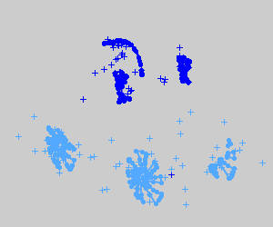
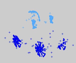
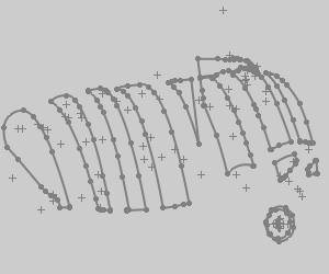
All of the geometry created so far is shown next.
-
Continue this process until you have created all of the desired geometry from the image.
(Pick a target area.Adjust the Number of Colors to create the desired results.Copy the geometry to a new layer, and repeat.)
Final Notes
Image Origin
You can change the location of the image in the graphics area using the Image Origin dialog.
To change the image location:
- Right-click Image -name, and click Edit.
- Set the Origin values (in relation to the WCS or world coordinate system).The Origin of the image is the lower-left corner.
- Click OK.The image is moved.
- To move any vectorized geometry to the new location, open the Vectorize... dialog, and click OK.
Warning: Only the original sketch associated to the image will be updated using this method.
Moving the image is helpful when you vectorize more than one image.
Image Size
In the Vectorize... dialog, the Image Size values are used to scale the vectorized geometry that is created.(The size of the image is not actually changed.)
Remove Arcs
If you want to create the vector geometry using only line segments, clear the ![]() With Arcs check box in the Vectorize... dialog.
With Arcs check box in the Vectorize... dialog.
Vectorize Parameters - Accuracy
The Accuracy parameter can be changed to create smoother or rougher contours.
High Accuracy (0.10 pixels)
Low Accuracy (0.90 pixels)
This concludes the tutorial.