


V-Carve Engraving
The V-Carve feature type is generally used to engrave text, arcs, lines and splines in a 3-dimensional form with 3 axis tool motion, with pocketing of open spaces in the selected profiles if necessary. There are two V-Carve operation types, Tapered Pocketing and V-Carve Finishing (engraving). This example uses the V-Carve Finishing operation.
Engraving a True Type font with V-Carve
Part 1) Open a new file
- Go to File > New to create a new part file.
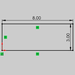
Part 2) Creating the Bounding Box
- Right-click the Front Plane and select Sketch.
- Choose Tools > Sketch Entities > Corner Rectangle.
- Starting at the origin, create a rectangle with values X = 8 and Y = 3 and click OK.
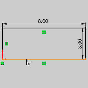
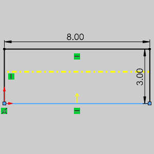
- Choose Tools > Sketch Tools > Offset Entities...
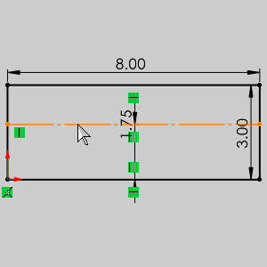
- Set the Parameters to 1.7500.
- Select the check box for Offset geometry under Construction geometry.
- Select the bottom line and use the Reverse option as necessary.
- Click OK and exit the sketch.
Part 3) Creating the Text
- Right-click the Front Plane and select Sketch to create a new sketch for our text.
- Choose Tools > Sketch Entities > Text...
- Select our offset line for the Curves.
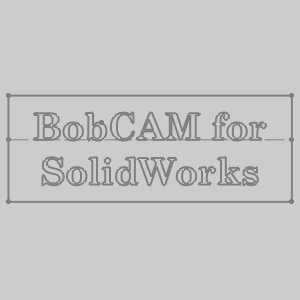
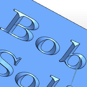
- In the Text field, type BobCAM for, press Enter and type SolidWorks.
- Make sure the Center Align option is selected and clear the check box for Use document font.
- Click Font.
The Choose Font dialog appears. - Set the Font to Century Schoolbook > Bold > Units = 0.750, and click OK.
The dialog closes. - Click OK to confirm our text and exit the sketch.
Part 4) Creating the Job
- In the CAM Tree, right-click CAM Defaults,and click New Job.
- With the Milling job type and the BC 3X Mill machine selected, and the Start Stock Wizard check box selected, click OK.
- Click the
 (next) button to skip the workpiece assignment.
Part 5) Create the Stock
- With Rectangular selected, the software automatically creates a bounding stock for the text in the graphics area.
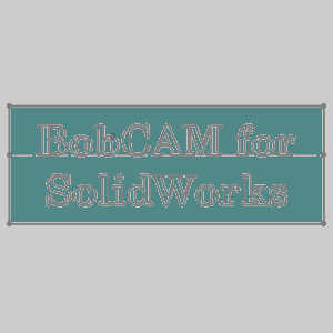
- Click to go to the Machine Setup.
Part 6) Set the Machine Setup and Work Offset
- For this example, we use the default origin location.
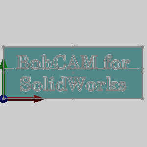
- In the Work Offset group, set the Z value to .000.
- Click OK.
Part 7) Creating the Feature
- In the CAM Tree, right-clickMachine Setup, and click Mill V-Carve.
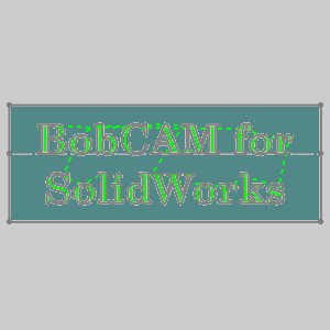
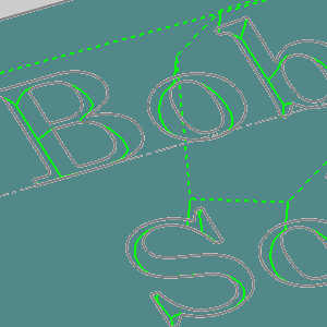
- In the Mill V-Carve Wizard,click the Select Geometry button.
- Click to select the text in the graphics area and click OK to confirm the selection and return to the wizard.
- Click Next>> to go to the Feature page.
- Note the Total Depth value. Setting the Total Depth value here sets the Pocket Depth value for the Tapered Pocketing operation (and the for the Finishing operation when using a V-Tool to pocket.) For this example, changing the depth does not change the toolpath calculation. For more information view the V-Carve Operation topic.)
- Click Next>> to go to the Machining Strategy. Notice under Current Operations, a single V-Carve Finishing operation is already selected.
Part 8) Set the Roughing Tool
- In the tree on the left, click V-Toolto go to the Tool page.
- For this example, we use the default 000 inch diameter V-tool.
Note the selected tool size does change the toolpath calculation for V-carve finishing operations.
Part 9) Set the Parameters
- Click Next>> to go to the Parameters. Notice under Depth Options, the V-Tool Depth of Cut parameter. This value is used to limit the depth when the width of the geometry profile is greater than the width of the tool. Again, we use the default settings for this example. For more information on specific parameters view the V-Carve Operation and the Mill Wizard topics.
- At the bottom of the wizard, click Compute.
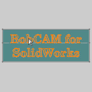
Part 10) Simulate
-
To view the toolpath simulation, right-click Milling Job and click Simulation.For more information on using simulation, view Getting Started with Simulation.
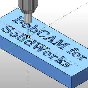
This concludes the example.