


How to Create a Multiaxis Feature
Introduction
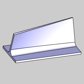
This tutorial explains how to create a Multiaxis feature. The goal of swarf milling is to create the desired cut using the entire flute length of the tool. This is great for machining fluid parts such as blisks (bladed disks) and impellers.
Example File
If you are connected to the Internet, the part file for this example can be downloaded automatically by clicking the following link: Example 1.sldprt
Once you download and saved the zip file, extract the files on your system in an easy place to remember. You can then open the file to use with this tutorial. All files for the tutorials in this help system available for download can be found by clicking on the following link: http://www.bobcad.com/helpfiles.
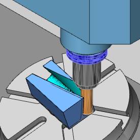
In the example file provided, the stock and Machine Setup are already defined for the part. The part is simulated using the BC Table Table machine.
This example uses the Automatic strategy and what is explained here can be applied to the other Swarfing strategies. Adding leads, creating multiple steps, adding a gouge check, and an important note on machine movement are also explained.
Part 1) Add the Feature
-
In the Property Manager, click the
 CAM Tree tab.
 -
Right-click
 Machine Setup and click Mill Multiaxis.
 -
In the Multiaxis Wizard, select Machining.
-
Click Next>>to go to the Posting dialog.
Part 2) Define the Posting Parameters
-
The Work Offset # is automatically set to the value defined in the Machine Setup dialog.
You can change the value here to update the Work Offset # for the feature. -
Click Next>>to go to the Multiaxis Postingdialog.
Part 3) Define the Multiaxis Posting Parameters
-
Notice, at the top of the dialog box, that the Use Machine Settings checkbox is selected.
This means that the Multiaxis Posting parameters for the feature use the same parameters as the machine that is selected in Current Settings.
You can clear the Use Machine Settings check box to define the Multiaxis Posting parameters of the feature separately from the current machine settings.
For this example, no changes are needed.
-
Click Next>> to go to the Tool page.
Part 4) Define the Tool Parameters
-
In the Tool Data group, set the Diameter to 0.75 and set the Corner Radius to 0.00.
Clear the System Toolcheck box, and set the Flute Length to 2.00.
 -
Click Assign Tool Holder. (If the Holder Label box displays the tool holder name, skip this step.)
In the Milling Tool Holder Library CAT 40 Holder list, click 0.75 inch I.D. Arbor CAT 40.
At the bottom of the dialog, click OK.
(If you assign a tool holder to a tool in the Tool Library, that holder is automatically assigned and Step 2 can be eliminated.)
-
Click Next>> to go to the Parameters dialog.
Part 5) Select Geometry
-
For this example, we are using the Automatic strategy because it always uses a Surface selection. (We use all of the Automatic options for and only change what is needed to get the desired result.)
-
Next to Surface, click
 .
.
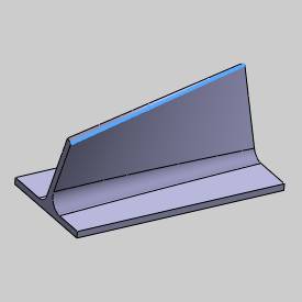
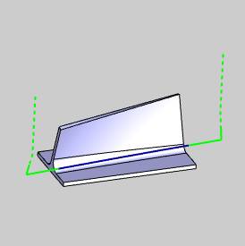
In the graphics area, select the swarf surface as shown next.
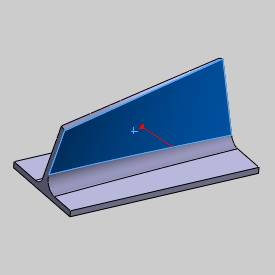
To confirm the selection, click ![]() OK.
OK.
-
The geometry selection for this example is now complete.
Note: The geometry selections for swarf machining change depending on the Strategy selected. With any strategy, you have the option to select the Upper and Lower Curves which are used to align the tool. The curves are split into equal-length segments and the matching points for each segment are used to create the tool orientation. Selecting the Upper and Lower Curves gives you control of the cutting side and direction for the feature. If you don't select the curves when using the Automatic strategy, the system attempts to find the correct curves and cutting direction automatically using only the selected swarf surfaces.
Part 6) Define the Parameters and Create the Toolpath
-
To leave material for finishing, in the Offset box, type 0.30.
-
At the top of the dialog, click Link.
-
Near the bottom of the dialog, click Retracts.
In the Clearance Area group, confirm that the Type is set to Plane, and the Direction is Z Axis.
Confirm that the Heightis set to 4.000.
This value is automatically set (but only when the feature is created) using the Clearance Plane value from the Machine Setup.
You can modify the Clearance Plane for the feature in this location at any time.
Click OK to close the Retracts dialog.
-
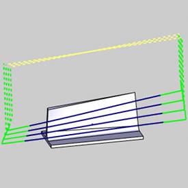
To view the feature as it is currently defined, at the bottom of the dialog, click Compute.
The result is shown next.
-
Notice that the toolpath computed on the wrong side of the part.
This is resolved in the next part of this tutorial.
For you, the toolpath may have calculated on the proper side of the part. If it did, then you do not have to change the Machining Side as explained in the next part.
Part 7) Edit the Feature
-
To edit the feature, in the CAM Tree, right-click
 Feature Multiaxisand click Edit.
 -
On the left side of the Multiaxis Wizard dialog, click Parameters.
In the Machining group, next to Side, click the arrow and select Left. -
At the bottom of the dialog, click Compute.
The toolpath is now on the proper side of the part.
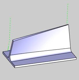
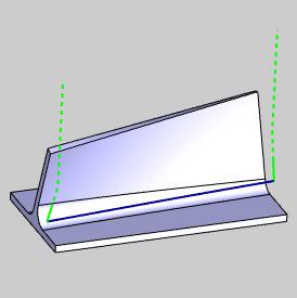
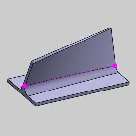
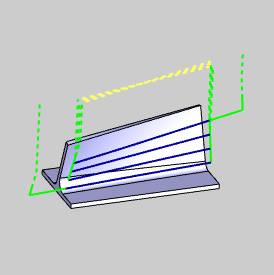
Tip: The Automatic options for machining work well for most parts. In the event that you have trouble creating the proper toolpath, you may want to turn on the Upper Curve and Lower Curve geometry items and assign the edges of the surface as shown next.

After selecting the Upper Curve and Lower Curve, you can then set the Machining Direction to Follow Lower Curve Chaining and set the direction of the lower curve as explained next.
-
To view the Start Point, in the CAM Tree,right-click
 Lower Edge Curve and click Modify Start Point. (You may need to expand the Geometry folder of the Multiaxis feature.)
 -
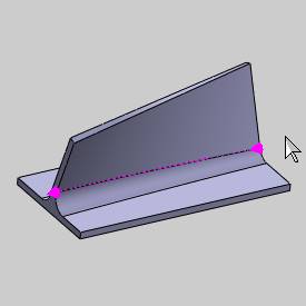
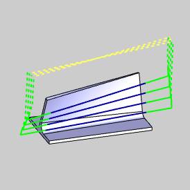
In the graphics area, the start point becomes visible.
To change the start point (direction), click near the end of the entity, and then click ![]() OK.
OK.
-
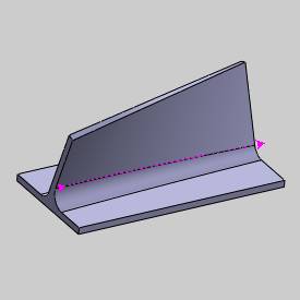
In addition to the previous method, to reverse the direction, you can right-click
Lower Edge Curve, and click Reverse Direction.
Part 8) Add Leads
Notice that the toolpath is plunging directly into the edge of the part geometry. This is not the desired result for this example. (To simulate the feature and review the result, in the BobCAM menu, click Simulation.) Next, you add a lead-in and a lead-out to cause the tool to plunge outside of the part, so that the side of the tool is used to begin the cut.
-
In the
CAM Tree, right-click Feature Multiaxis,and click Edit.
On the left side of the dialog, click Parameters.
At the top of the dialog, click the Linktab. -
In the Entry/Exitgroup, next to First Entry, (on the right side) select Use Lead-In.
Next to Use Lead-In, click ![]() to open the Lead-in dialog.
to open the Lead-in dialog.
Notice at the top of the dialog, that the ![]() Use Default Lead-In check box is selected.
Use Default Lead-In check box is selected.
To close the dialog, click OK.
-
In the Entry/Exit group, next to Last Exit, (on the right side) select Use Lead-Out.
-
At the bottom of the dialog, click Default Lead-In/Out.
The Default Lead-In/Out dialog displays.
In the Lead-Ingroup, next to Type, select Tangential Line.
At the top of the dialog, next to Copy, click ![]() .
.
This copies the Lead-In settings to the Lead-Out group.
To finish and close the dialog, click OK.
-
In the Multiaxis Wizarddialog, click Compute.
The result is shown next.
-
To view the result, in the BobCAMmenu, click
 Simulation.
To learn more, view Getting Started with Simulation.
-
To close simulation, in the BobCAMmenu, click
 Exit Simulation.
Part 9) Create Multi Cuts
Now instead of cutting the part with a single slice, multiple slices are created using Multi Cuts.
-
Edit the feature, click Parameters,and click the Multi Cuts tab.
In the Pattern Slices group, in the Depth Stepsbox, type 4.
Click Compute.
-
Notice that the retract moves are again within the bounds of the part. (This is for all links that are not the first entry or the last exit.)
To change this result, Edit the feature, and click the Linktab. -
In the Links Between Slicegroup, next to Large Moves,select Use Lead-In/Out (on the right side).
Once selected, click ![]() to open the Lead-In/Out dialog.
to open the Lead-In/Out dialog.
Notice that the ![]() Use Default Lead-In/Out check box is selected.
Use Default Lead-In/Out check box is selected.
To close the dialog, click OK.
-
In the Multiaxis Wizard, click Compute.
Now all depth steps use the same lead-in and lead-out as the first entry and last exit moves.
New to , you can now define Extensions for the toolpath in addition to, or instead of using leads. You can define the length to extend the start and end of the toolpath separately or you can define a starting angle from the swarf surface for the start of the toolpath. This is shown at the end of this tutorial.
Part 10) Add a Gouge Check
There may be times when you want to use machining even though the machining surfaces are not truly flat. This could result in gouging the surface if the feature is defined too close to the target surface. In such a scenario, you can use a feature to get as close as possible to the target surface before applying a different strategy to finish the part. The Gouge Check can be used to push the tool out of swarf, or away from the target surface. This means that the tool is moved away from the surface by drawing a line between the contact points of the upper and lower rail; the tool is moved away at a right angle to this line.
-
Edit the Multiaxis feature, click Parameters,and click the Gouge Checktab.
-
In the Gouge and Excess group, select the
 Check Against Surfaces check box, and confirm that the Degouge option is selected.
(You must have selected at least one surface to use this check.) -
If there are additional surface that you want to gouge check, select the
Additional Check Surfaces check box.
Click to enable selection mode, and select the geometry that you want to gouge check (and then click  OK to confirm the selection).
This can be the part geometry or any other geometry in the graphics area. -
To update the feature, click Compute.
Part 11) Minimize Table Rotations
When creating features, there may be fast machine movements that need to be minimized. The following option is provided to help reduce these movements.
-
Edit the Multiaxis feature, click Parameters,and click the Tool Axis Controltab.
-
Select the
Minimize Rotation Axis Changes check box. -
To update the change, click Compute.
-
To view the result, on the BobCAMtoolbar, click
Simulation.
This result is a significant reduction of heavy machine movement for the feature.
Part 12) Add Extensions to the Toolpath
-
Edit the feature and click Parameters.
-
At the bottom of the dialog, in the Extensions group, type 1.00in both the Start and End boxes.
This extends the lead-in and lead-out by the specified value. (You can use these options with or without leads defined for the feature.) -
Compute the toolpath.
This concludes the tutorial.