


How to Create a Multiaxis Wireframe Operation
Introduction
This tutorial explains how to create a Multiaxis Wireframe operation. The wireframe operation requires a Drive Curve selection to define the toolpath and Orientation Lines selection along the curve to define the tool orientation.
Example File
If you are connected to the Internet, the part file for this example can be downloaded automatically by clicking the following link: Multiaxis WireframeExample 1.sldprt
Once you download and saved the zip file, extract the files on your system in an easy place to remember. You can then open the file to use with this tutorial. All files for the tutorials in this help system available for download can be found by clicking on the following link: http://www.bobcad.com/helpfiles.
In the example file provided, the stock and Machine Setup are already defined for the part. The part is simulated using the BC Table-Table machine.
In this example, you apply a trim cut to the bottom surface of the part. This example explains how to create all the geometry that is needed for the feature directly from the part model. You also learn how the chain direction of the drive curve and orientation lines define the toolpath. An important section here explains how to set the side tilt angle to create the proper tool orientation for the feature. The last part shows how to force the tool past the drive curve in order to cut with a different part of the flute.

Part 1) Add the Feature
-
In the Property Manager, click the
 CAM Tree tab.
 -
Right-click
 Machine Setup and click Mill Multiaxis.
 -
In the Multiaxis Wizard, click Wireframe.
-
Click Next>>to go to the Posting dialog.
Part 2) Define the Posting Parameters
-
The Work Offset # is automatically set to the value defined in the Machine Setup dialog box.
You can change the value here to update the Work Offset # for the feature. -
Click Next>>to go to the Multiaxis Postingdialog box.
Part 3) Define the Multiaxis Posting Parameters
-
Notice, at the top of the dialog box, that the Use Machine Settings checkbox is selected.
This means that the Multiaxis Posting parameters for the feature use the same parameters as the machine that is selected in Current Settings.
You can clear the Use Machine Settings check box to define the Multiaxis Posting parameters of the feature separately from the current machine settings.
An example usage is explained later.
-
Click Next>> to go to the Tool page.
Part 4) Define the Tool Parameters
- In the Tool Data group, set the Diameterto 0.375 and the Corner Radius to 0.00.
- To assign a tool holder, click Assign Tool Holder. (If the Holder Label already displays the holder name, you can skip this step).
In the Milling Tool Holder Library,in the CAT 40 Holder list, click 0.375 inch I.D. Arbor CAT 40,and click OK. - Click Next>>to go to the Parameters dialog.
Part 5) Select Geometry
- On the Surface Paths tab, in the Edit Curves group, click Drive Curves.
Part 6) Set the Direction of the Orientation Lines
You must confirm that all of the OrientationLines share the same chain direction. For this example, all of the Orientation Lines must point towards the outside of the part.
-
To view the chain direction, first clickFinish to close the wizard.
-
In the feature in the
CAM Tree, right-click  Orientation Linesand click Modify.
(You may need to expand the Geometry folder under the
 Multiaxisoperation.)
 -
The start point of each orientation line is now visible in the graphics area.
-
To change the chain direction, click near each entity in the desired direction as shown next.


-
Continue this process until the direction of all orientation lines point to the outside of the part.


-
To accept the changes,
 Property
 OK.
OK.

Tip: As shown in this example, the chain direction of the Orientation Lines is set to start at the tool tip and point back towards the spindle. The chain direction does not point towards the tool tip.
If an error message displays a warning about antiparallel lines, then all of the Orientation Lines are not pointing in the same direction. Repeat Modify Start Point and correct the backwards chain direction.
Part 7) Set the Direction of the Drive Curve
-
The chain direction of the drive curve must also be set.
The Drive Curve chain direction must be set to properly define the cutting direction and side based on the feature(open or closed) and the selected operation parameters.
To properly set the direction, first

-
To hide the part, in the
 Feature Manager design tree, click Part Model and click
 Hide.
Hide. -
To view the chain direction, in the
CAM Tree, right-click Drive Curves, and click Modify.
You may need to zoom-in to view the start point.
-
Confirm that the chain direction is counter-clockwise as shown in the previous image.
Regardless of the current direction, click ![]() OK.
OK.
If the direction was clockwise, right-click ![]() Drive Curves,and click Reverse Direction.
Drive Curves,and click Reverse Direction.
Part 8) Define the Parameters
-
Right-click
 Feature Multiaxis and click Edit.
Click Parameters.
In the Pattern group, the Maximum Snap Distance defines what Orientation Lines are included in the toolpath calculation. This distance is measured from the selected Drive Curve.
For this example, because the orientation lines touch the drive curve, the default value of 0.100is used.
-
Because the chain direction is counter-clockwise (using the
-
In the Sorting group, next to Direction for One Way Machining,select Follow Curve Chaining.
-
To create the feature toolpath, at the bottom of the dialog, click Compute.
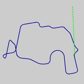
The toolpath is currently at the selected drive curve edge, which is not the desired result.
To view the location of the toolpath compared to the drive curve, in the CAM tree, click Drive Curves.
The drive curve preview displays in the graphics area.
Currently the tool orientation is not the same as the selected Orientation Lines. The Tool Axis Control contains a tilting parameter, Tilt Away from Line, that determines the amount of side tilting applied to the tool from the Orientation Lines in the direction of cut.
Important: In order to have the tool orientation follow the same orientation of the selected Orientation Lines, you must define the Tilt Away from Line parameter as 0.00 degrees.
Part 9) Define the Side-Tilt Angle
-
Edit the feature, and click Parameters.
-
Click the Tool Axis Control tab.
Notice the tilting strategy, next to Tool Axis Will, is set to Be tilted relative to cutting direction. -
In the Tilt Away from Line box, type 0.000.
-
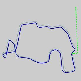
To calculate the toolpath, click Compute.
The toolpath is now offset to the bottom side of the part. This is the desired result.
(To show the part, in the ![]() Feature Manager design tree, clickPart Model and click
Feature Manager design tree, clickPart Model and click ![]() Show.)
Show.)

-
To view the simulation,
 Simulation
During simulation, the tool orientation is now the same as the Orientation Lines.

-
To close simulation,
 Exit Simulation
Adjust the Machine Table Rotation
When you simulate the program, the machine table is sometimes rotated in a way that doesn't allow you to view the part without rotating the view of the machine. You can change the Angle Pair settings for the feature to modify the table rotation used in simulation and in the posted code.
- To edit the feature, in the CAM
Tree, right click Feature Multiaxis,
and click Edit.
- Click the
Multiaxis Posting icon in the tree.
- Clear the Use
Machine Settings check box.
- In the Angle
Pair group, next to Use,
select Other Solution.
When you simulate the program again, you can now view the part being cut from the opposite side of the machine.
The table is rotated to use the other solution to the rotation angles of the primary and secondary rotary axes (angle pair). This changes the posted output of the program as well as the simulation.
Tip: You don't have to compute the toolpath to update this setting for simulation, but you must Post the program to update the code if has already been posted.
Part 10) Axial Shift
If you want to force the tool past the drive curve in order to cut using more of the flute, or a different part of the flute, you can use the Axial Shift parameters.
-
Edit the feature, click Parameters,and click the Utility tab.
-
In the Axial Shift group, notice the option Constant for Each Contour.
This shifts the tool by the specified amount for the entire toolpath. -
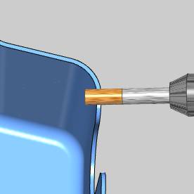
In the Tobox, type -0.250.
(Negative values cause the tool to in-feed, and positive values retract the tool.) -
To add the changes, click Compute.
The result is visible in the toolpath display.
The following images show the tool position before and after adding the Axial Shift.
| Before | After |
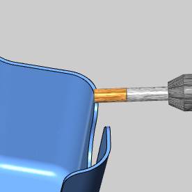
|
|
This concludes the tutorial.
Related Topics
Multiaxis Wireframe