


The Advanced UI Link Tab
Introduction
This topic explains the Link tab of the Advanced UI for the following operations:
-
Advanced Rough
-
Flatlands
-
Equidistant
-
Pencil
-
Advanced Planar
-
Project Curves
-
Advanced Z Level Finish
-
Steep Shallow
The Link Tab
The Link tab of the Advanced UI contains all of the parameters for defining the link moves. Separate sections are provided that allow specific control based on the type of move. The parameters are used in conjunction with the Retracts andDefault Lead-In/Out dialogs.
Parameters
Entry/Exit
-
First entry
-
Approach from clearance area - uses the area specified in the Retracts dialog box.
-
Approach from rapid distance - uses the rapid distance specified in the Retracts dialog box.
-
Approach from feed distance - uses the feed distance specified in the Retracts dialog box.
-
 Direct
- applies an approach to the drive surface with no lead-in or lead-out.
The feedrate is rapid. The tool axis orientation during direct entry
is the Z-axis.
Direct
- applies an approach to the drive surface with no lead-in or lead-out.
The feedrate is rapid. The tool axis orientation during direct entry
is the Z-axis.
-
-
Last exit
-
Retract to clearance area - uses the clearance distance specified in the Retracts dialog box.
-
Retract to rapid distance - uses the rapid distance specified in the Retracts dialog box.
-
Retract to feed distance - uses the feed distance specifies in the Retracts dialog box.
-
Retract
to clearance area through tube center - retracts the
tool to the Clearance Area through the center of a tube. This option is not used for 3 Axis features.
-
Direct
- applies an exit from the drive face with no lead-in or lead-out.
The feedrate is rapid. The tool axis orientation during direct exit
is the Z-axis.
-
Retract to Incremental Clearance Plane - uses the specified incremental clearance distance from the Retracts dialog box. This allows you to reduce clearance movements when the tool can safely perform rapid movement below the clearance plane.
-
Note: The tool Home Position for the feature is specified in the Retracts dialog which is accessed from the Link tab. You must first select one of the following options to make the XYZ home position values available in the Retracts dialog box.
-
Start from Home Position
 Select the check box to start the approach from the home position.
 Clear the check box when not starting the approach from the home position.
 -
Return to Home Position
Select the check box to return the tool to its home position after the
operation.
Clear this check when not sending the tool to the home position after
the operation. -
Start from / Return to Max Z - This option does not affect 3 Axis toolpaths
Area Links
This group is available when using the Advanced Rough and Flatlands toolpaths, and controls movements between cuts in the same area.
-
Within group / Between groups - Within group specifies connection moves between the offset cuts in a single group. Between groups specifies connection moves between the different groups inside a single region on the same cutting layer.
-
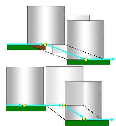
Direct
- treats the gap as if it doesn't exist and links the toolpath segments
directly with no retract.
-
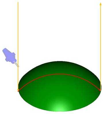
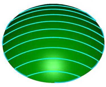
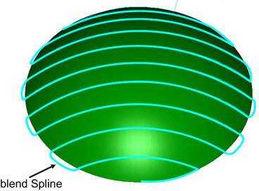
Blend
spline - creates a spline that is blended between the two
surfaces to link the toolpath segments:
-
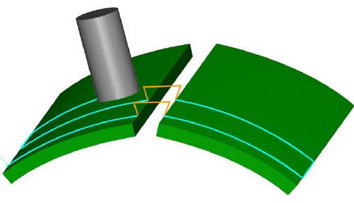
Retract
to feed distance - causes the tool to retract to the Feed
distance value before connecting to the next toolpath segment.
-
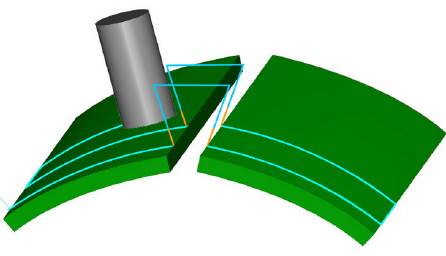
Retract
to rapid distance - causes the tool to retract to the Rapid
distance value before connecting to the next toolpath segment.
-
Retract
to clearance area - causes the tool to retract to the Clearance
area before connecting to the next toolpath segment.
-
Clearance blend spline - enables two contours to be linked with a new blend spline. This option is only available for the Advanced Rough and Flatlands toolpaths.
-

Gaps along cut
This group is not available when using the Advanced Rough and Flatlands toolpaths.
-
Small gaps / Large gaps - The Small Gaps and Large Gaps items share the same options as listed next.
-
Direct
- treats the gap as if it doesn't exist and links the toolpath segments
directly with no retract.
-
Follow
surfaces - attempts to follow the geometry surface and
create a toolpath as if the geometry is closed.
-
Blend
spline - creates a spline that is blended between the two
surfaces to link the toolpath segments:
-
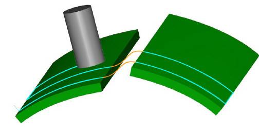
Step
- creates a step to link toolpath segments when needed.
-
Shortest path
- This option creates links at the specified air move safety distance height. The links follow the shape of the machining surface to avoid undesired tool retracts and prevent scratches to the finishing surface.
-
Retract
to feed distance - causes the tool to retract to the Feed
distance value before connecting to the next toolpath segment.
-
Retract
to rapid distance - causes the tool to retract to the Rapid
distance value before connecting to the next toolpath segment.
-
Retract
to clearance area - causes the tool to retract to the Clearance
area before connecting to the next toolpath segment.
-
-
Small Gap Size - sets the threshold size for small gaps in one of two ways.
-
In % of Tool Diameter - is a percentage of the tool diameter.
-
As Value - determines the actual size of small gaps.
-

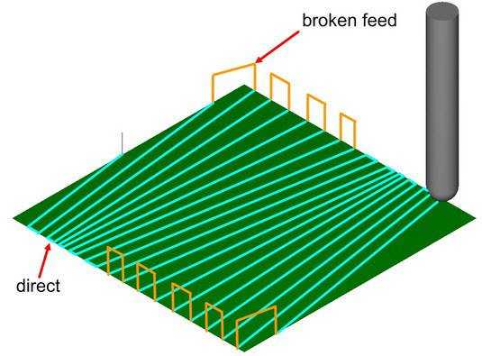
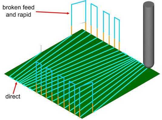
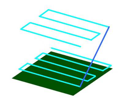
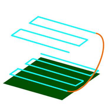
Note: The following image shows small gaps (3) with
Direct selected, and large gaps (4) with Retract to Feed Distance (2).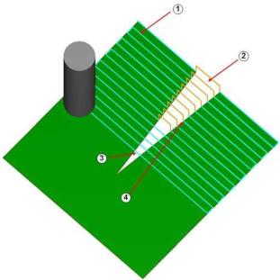
Links between slice
When using the Advanced Rough and Flatlands toolpaths, there are no separate options for small moves and large moves.
-
Small gaps / Large gaps - The Small Gaps and Large Gaps items share the same options as listed next.
-
Direct
- links the toolpath segments directly with no retract.
-
Follow
surfaces - links the toolpath segments by following the
surface. You must have gouge checking activated to use this option.
-
Blend
spline - creates a spline that connects the two toolpath
segments.
-
Step
- creates a step to link toolpath segments when needed.
-
Shortest path
- This option creates links at the specified air move safety distance height. The links follow the shape of the machining surface to avoid undesired tool retracts and prevent scratches to the finishing surface.
-
Retract
to feed distance - causes the tool to retract to the Feed
distance value before connecting to the next toolpath segment.
-
Retract
to rapid distance - causes the tool to retract to the Rapid
distance value before connecting to the next toolpath segment.
-
Retract
to clearance area - causes the tool to retract to the Clearance
area before connecting to the next toolpath segment.
-
Clearance blend spline - enables two contours to be linked with a new blend spline. This option is only available for the Advanced Rough and Flatlands toolpaths.
-
-
Small Move Size - sets the threshold size for small moves in one of two ways.
-
In % of Tool Diameter - is a percentage of the tool diameter.
-
As Value - determines the actual size of small moves.
-
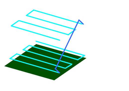
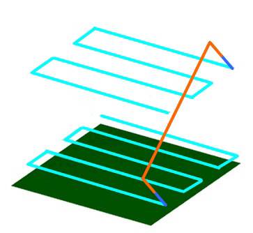
Note: The following image shows small moves (1)
with Direct selected, and large gaps (2) with Retract to Feed Distance.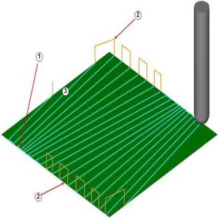
Links Between Passes
This group becomes available when using the Multi passes option found on the Roughing tab of the Advanced Planar toolpath.
-
Small moves / Large moves - The Small Gaps and Large Gaps items share the same options as listed next.
-
Direct
- links the toolpath passes directly with no retract.
-
Follow surfaces - links the toolpath passes by following the surface.
-
Blend
spline - creates a spline that connects the two toolpath
passes.
-
Step
- creates a step to link toolpath passes when needed.
-
Shortest path
- This option creates links at the specified air move safety distance height. The links follow the shape of the machining surface to avoid undesired tool retracts and prevent scratches to the finishing surface.
-
Retract
to feed distance - causes the tool to retract to the Feed
distance value before connecting to the next toolpath pass.
-
Retract
to rapid distance - causes the tool to retract to the Rapid
distance value before connecting to the next toolpath pass.
-
Retract
to clearance area - causes the tool to retract to the Clearance
area before connecting to the next toolpath pass.
-
-
Small Move as Value - sets the threshold size for small moves.
Links Between Regions
This group becomes available when using the Advanced Rough and Flatlands toolpaths.
-
Direct
- links the toolpath passes directly with no retract.
-
Blend
spline - creates a spline that connects the two toolpath
passes.
-
Retract
to feed distance - causes the tool to retract to the Feed
distance value before connecting to the next toolpath pass.
-
Retract
to rapid distance - causes the tool to retract to the Rapid
distance value before connecting to the next toolpath pass.
-
Retract
to clearance area - causes the tool to retract to the Clearance
area before connecting to the next toolpath pass.
-
Clearance blend spline - enables two contours to be linked with a new blend spline. This option is only available for the Advanced Rough and Flatlands toolpaths.
Leads
Next to all of the Link options that are described in this help topic are the following lead options. When using the Advanced Rough, or Flatlands toolpaths, the lead options are replaced with ramp options.
-
Use Lead-In - select this option to use a lead-in only.
-
Use Lead-Out - select this option to use a lead-out only.
-
Use Lead-In/Out - select this option to use a lead-in and lead-out.
-
Don't use Lead-In/Out - select this option if no leads are needed.
-
Use ramp - select this option to use a ramp entry.
-
Don't use ramp - select this option if no ramp is needed.
Once you have set any of these options to
use leads, click  to
access the Leads parameters. Leads are explained in the Lead-In
Dialog topic.
to
access the Leads parameters. Leads are explained in the Lead-In
Dialog topic.
Other Options
-
Click Retracts to open the Retracts dialog box with various clearance plane and distance parameters.
-
Click Default Lead-In/Out to open the Default Lead-In/Out dialog.