


 Options: Advanced Rough
Introduction
This topic explains the Options page of the Advanced Rough operation found in the 3 Axis Wizard, the options found in it, and will provide links to related topics.
Note: Click on the images in this topic in order to see the animation, or an enlarged version.
Operation Stock
The Advanced Rough operation always uses a stock recognition for the toolpath calculation. By default, the stock definition from the Stock Wizard is used. You can also specify the stock to use by assigning geometry to the Operation Stock item in the CAM Tree. Operation stock allows you to remove unnecessary air cutting from the operation by passing stock for only the area that you want to cut. There are no settings needed in the wizard to use stock recognition for the Advanced Rough operation. The stock definition from the Stock Wizard is always used unless you assign Operation Stock.(View Selecting Operation Stock for more help.)
Tip: You can use simulation to save the stock model as an .stl file, which can then be used as Operation Stock. To learn more, view How to Save Simulation Stock as STL.
 Options
Rest Roughing
Note: Rest Roughing is unavailable when using the Automatic 3+2 (5 Axis) Method in the Tool Axis Control page.
Calculates the toolpath to remove all the non-machined areas remaining
from the previous roughing tool. The previous tool is used to
identify accurately the areas on a 3D component by sweeping the diameter
across the whole part being machined. In this way any non-machined
areas are identified and passed to the system and the toolpath is
calculated. The Rest Roughing toolpath does not require the whole
part to be machined again. It machines only those areas that are left
behind by the previous tool. On intricate parts, multiple rest rough
toolpaths are required to remove as much material as possible before
running semi finishing or finishing toolpaths. In Rest Roughing toolpaths
you normally use a smaller step down (as the cutter size reduces)
than the cutter used for the previous roughing toolpath. The following
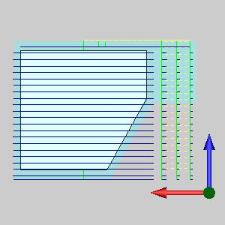
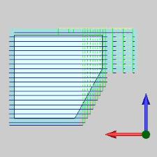
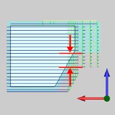
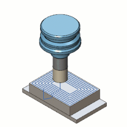
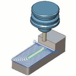
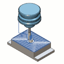
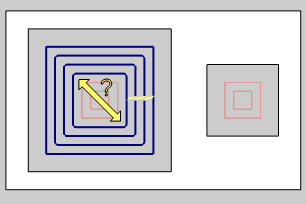
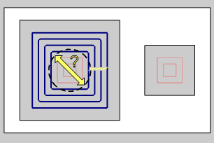
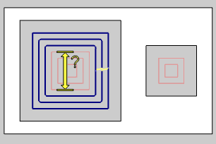
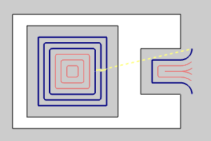
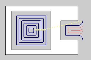
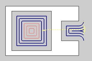
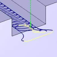
is an example of using the Advanced
Rough feature for rest machining,
along with an image showing the rest roughing strategy in blue.


![]() - With this check box cleared, Rest Roughing will not be used.
- With this check box cleared, Rest Roughing will not be used. ![]() - With this check box selected, Rest Roughing will be used, and the following options will become available to allow you to specify how the rest roughing is to be handled.
- With this check box selected, Rest Roughing will be used, and the following options will become available to allow you to specify how the rest roughing is to be handled.
Note: The Use Previous Operation check box doesn't display unless you have another operation previous to the current operation in the feature.
- Use
Previous Operation
 - Clear the check box to manually enter the tool parameters of the previous
roughing operation.
- Clear the check box to manually enter the tool parameters of the previous
roughing operation. - Select the check box to have the system automatically set the Rest Roughing
parameters using the tool parameters of a roughing operation that is previous
to this operation in the feature.
- Select the check box to have the system automatically set the Rest Roughing
parameters using the tool parameters of a roughing operation that is previous
to this operation in the feature.- Previous
Tool Diameter - set this to the
diameter of the previous tool used to rough the part. This value must
be larger than the tool being used for the rest roughing operation.
- Previous
Tool Corner Radius - set this to
the corner radius of the previous tool used to rough the part.
- Previous
Offset Type - The Offset Type determines if the allowance from
the previous operation was applied to the entire model or separately
for the bottom and sides of the part. Select one of the following
options and then type the allowance value used in the available allowance
boxes.
- Global
- calculates the toolpath applies a single allowance value
to the entire model using the Allowance XYZ value.
- Allowance
XYZ - is the amount of material left on the
entire model (XYZ).
- Allowance
XYZ - is the amount of material left on the
entire model (XYZ).
- Side
and Bottom - allows you to specify separate allowances
for the side (XY) and bottom (Z) of the part.
- Side
Allowance - is the amount of material left
on the sides of the part (XY).
- Bottom
Allowance - is the amount of material left
on the bottom of the part (Z).
- Side
Allowance - is the amount of material left
on the sides of the part (XY).
- Global
- calculates the toolpath applies a single allowance value
to the entire model using the Allowance XYZ value.
- Detect stock thicker than - allows you to focus the toolpath on stock consisting of a particular range of thickness. Setting a value here will force the toolpath to ignore any stock whose thickness does not meet or exceed this value.
- Previous
Tool Diameter - set this to the
diameter of the previous tool used to rough the part. This value must
be larger than the tool being used for the rest roughing operation.
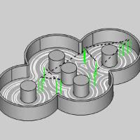
Machine Flatlands
Flatlands
is designed to finish flat areas of a part, and it is best suited for
machining large flat areas at multiple Z-levels.
![]() - Clear this check
box to not allow flatland machining.
- Clear this check
box to not allow flatland machining.![]() - Select this check
box to allow flatland detection which creates an optimized finishing toolpath
for flat areas.
- Select this check
box to allow flatland detection which creates an optimized finishing toolpath
for flat areas.
- Min.
Width of Flatlands - sets the minimum width of flat areas that
are included in the flatlands machining.
- Max. Width
of Flatlands - sets the maximum
width of flat areas that are included in the flatlands machining.
- Clear the check box to only set a minimum width of flat areas that are
included. - Select the check box to set a maximum width of flat areas that are included.
Important: The Flatlands feature must use flat-end mills or bullnose mills.
|
|
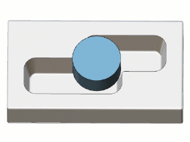
Boundary Options
Boundaries are used to contain the toolpath of the operation to stay within the specified area. The Boundary Options determine where the tool cuts when it reaches the boundary in one of three ways.
-
 Center of
Tool - forces the center of the tool to cut directly on the
specified boundary.
Center of
Tool - forces the center of the tool to cut directly on the
specified boundary.

-
 Tool Inside
- forces the entire tool to stay inside of the boundary. (This offsets
the toolpath to the inside of the boundary by the tool radius.)
Tool Inside
- forces the entire tool to stay inside of the boundary. (This offsets
the toolpath to the inside of the boundary by the tool radius.)

- Offset - is used to add an additional offset to the location of the tool at the boundary when using Tool Inside or Tool Outside. When using Tool Inside, the tool stays inside of the boundary by the specified distance. When using Tool Outside, the tool goes outside of the boundary by the specified distance. Note that positive or negative values are supported.
-
Tool Outside
- forces the entire tool to go outside of the boundary. (This offsets
the toolpath to the outside of the boundary by the tool radius.)

- Offset - is used to add an additional offset to the location of the tool at the boundary when using Tool Inside or Tool Outside. When using Tool Inside, the tool stays inside of the boundary by the specified distance. When using Tool Outside, the tool goes outside of the boundary by the specified distance. Note that positive or negative values are supported.
Stock
- Stock Has Undercuts - allows you to trim the toolpath to account for voids below the first cuts made to the stock.
- Once a cut is applied to the stock, all cuts under that location are also made. - Each depth of cut is checked to ensure there is stock to be removed, and toolpath is trimmed as needed if no stock is found.
- Axial Shift - offsets the trimmed area down so additional cuts are made.
|
|
|
+ Axial Shift |
|
|
|
Other
-
Advanced - Click the Advanced button to open the Roughing Advanced page.
Roughing Advanced
Smoothing
This group is available when the Cut Pattern on the Patterns page is set to Offset Out, Offset In, or Morph Spiral. When the Parallel option is selected, only the Smooth Final Contour option is available in this group.
- Smooth Corners
- Select the check box to create fillets in the sharp corners
of the toolpath. The fillet is not applied to the outer contour as it
is with Smooth Final Contour. When selected, the Smooth Distance/Stepover
% parameter becomes available as well as the Smooth Final Contour option.
- Clear the check box to turn off Smooth Corners.- Smooth Distance/Stepover % - With the Smooth Corners check box selected, the Smooth Distance/Setpover % sets the
radius of the fillet as a percentage of the stepover distance.
- Smooth Distance/Stepover % - With the Smooth Corners check box selected, the Smooth Distance/Setpover % sets the
radius of the fillet as a percentage of the stepover distance.
- Smooth Final Contours - This option becomes available when the Smooth Corners option is also selected. - With the check box cleared, the Smooth Final Contour option is not used.
- Select the check box to create fillets in the sharp corners of outer contours.
The Smooth Distance/Stepover % parameter becomes available.
- Smooth Distance/Stepover
% - sets the radius of the
fillet as a percentage of the stepover distance.
- Smooth Distance/Stepover
% - sets the radius of the
fillet as a percentage of the stepover distance.
- Smooth Contours - With the check box cleared, the Smooth Contours option is not used.
- Select the check box to smooth the offset pattern based on the Deviation/Stepover % allowance, which becomes available when this option is selected.
- Smooth Deviation/Stepover
% - sets the allowable deviation from the original offset pattern.
- Smooth Deviation/Stepover
% - sets the allowable deviation from the original offset pattern.
- Smooth Links
-
Select the check box to smooth the links within a group. The last segments
of the previous contour and the first segments of the next contour are
trimmed. The connecting link connects diagonally. In the case of an S-Link
the connection is an S-type link.
- Clear the check box to turn off Smooth Links.- Gap
Size/Stepover % - With the Smooth Links check box selected, the Gap Size/Stepover % sets the distance over which the s-link
moves are applied as a percentage of the stepover amount.
- Gap
Size/Stepover % - With the Smooth Links check box selected, the Gap Size/Stepover % sets the distance over which the s-link
moves are applied as a percentage of the stepover amount.
- Start Points
- With this check box cleared, no special consideration will be made when beginning the next pass. - With this check box selected, the start of the next pass will be shifted by the specified amount. - Shift Distance/Stepover % - allows you to set a distance that will force each pass to be started the specified distance further along than the last was started.
- Shift Distance/Stepover % - allows you to set a distance that will force each pass to be started the specified distance further along than the last was started.
- Minimize Links - When using the Offset Pocket Out and the Morph Spiral Advanced Pocket patterns this option can be selected to help keep the tool down for as much of the operation as possible.
With this check box selected, the links are adjusted in a way which attempts to use part of the actual toolpath contour for linking instead of applying retraction moves.
With this check box cleared, no additional optimizations will be attempted on the links. Minimize LinksMinimize Links
Others
This group is available when the Cut Pattern on the Patterns page is set to Offset Out, Offset In, or Morph Spiral.
- Avoid Air Machining
- With the check box cleared, the stepover will be continued over the entire part. This can result in cuts being made to areas which already have stock removed. - With the check box selected, toolpath will be terminated in areas which have already been cleared of stock. Avoid Air Machining Avoid Air Machining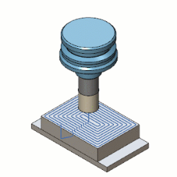
- Remove Corner Pegs
- Clear the check box to turn off Remove Corner Pegs. - Select the check box to add extra
tool movement in corners, removing the rest material; for use when a stepover
greater than 50 percent results in small pegs of material remaining in
the corners. With this check box selected, you will be able choose between the following three options. - Line-Arc-Line - removes the corner pegs with an arc between two lines as seen in the animation below.

- Corner Peg Height in % of Tool Diameter - sets the size of the corner peg based on a percentage of the tool size in use.
- Corner Peg Height in % of Tool Diameter - sets the size of the corner peg based on a percentage of the tool size in use.
- Arc - removes the corner pegs with a single looping arc motion as seen in the animation below.
- Corner Peg Height in % of Tool Diameter - sets the size of the corner peg based on a percentage of the tool size in use.
- Corner Peg Height in % of Tool Diameter - sets the size of the corner peg based on a percentage of the tool size in use.
- Line - removes the corner pegs by moving away from, and back to the toolpath with a straight line as seen in the image below.

- Corner Peg Height in % of Tool Diameter - sets the size of the corner peg based on a percentage of the tool size in use.
- Corner Peg Height in % of Tool Diameter - sets the size of the corner peg based on a percentage of the tool size in use.
- Line-Arc-Line - removes the corner pegs with an arc between two lines as seen in the animation below.


Stepover
This group is only available when Adaptive Roughing is selected on the Patterns page.
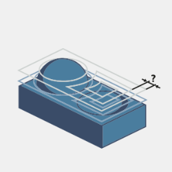
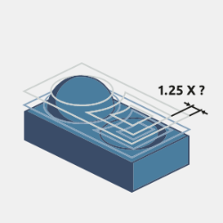
- Dependent Desired Stepover - This feature lets you avoid the hard coded dependency between the maximum and desired stepovers in the adaptive roughing pattern. The desired stepover parameter can take any value which is less than the maximum one. The hard coded value is 1.25 x maximum stepover.
- With this check box cleared, you can list a Desired Stepover, which must be lower than the previously specified (Maximum) Stepover. - With the check box selected, the Desired Stepover will be set so the specified (Maximum) Stepover will be 1.25 times greater.Dependent Desired StepoverDependent Desired Stepover
Thin Wall Processing
This group is only available when Adaptive Roughing is selected on the Patterns page.
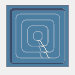
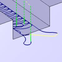
- Thin Wall Rollover
- With this check box cleared, toolpath calculation will not attempt to optimize settings in cases where thin walls of material are created. In these cases, the toolpath will continue to loop away and come back to reengage. - With the check box selected, toolpath calculation attempts to optimize cutting where thin walls are created by continuing around the wall to engage from the other side. This helps to eliminate air cutting.Thin wall created during machining 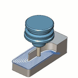 Thin Wall Rollover Thin Wall Rollover
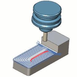
Region Processing
This group is only available when Adaptive Roughing is selected on the Patterns page.
- Over Machine - Optimizes the milling conditions for hard metal milling to compensate for long tool deflections and cutting forces.
- With this check box cleared, toolpath calculation will not attempt to optimize for tool deflections. - With the check box selected, toolpath calculation attempts to optimize cutting to avoid chatter caused by thin walls generated due to tool deflections. Over Machine Over Machine
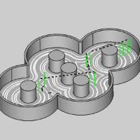
- Remove Stock Pillars
- With this check box cleared, toolpath calculation can result in open areas ending in thin walled areas in the center which can create adverse cutting conditions. - With the check box selected, toolpath calculation optimizes to leave a wide pillar in the center which is then handled with a spiral ramp motion in order to create optimal cutting conditions and help extend tool life. Remove Stock Pillars Remove Stock Pillars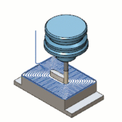
Remove Small Regions/Contours
These options allow you to remove small pockets and segments which are not necessary to machine. The size of these segments must be defined as a percentage of the tool diameter. (Threshold Value in % of Tool Diameter)
-
Filter by - These options allow you to determine the type of areas being considered for elimination. The Filter by options are only available when using the Offset Out, Offset In, and Morph Spiral cut pattern options.
-
 Regions - A region can be defined as an area which can be handled without the need for a retract to clearance move. By selecting regions to filter, areas under the specified value will be ignored.
- Contours - A contour can be defined as a single pass around a region before a link move is needed for the next pass. By selecting contours to filter, passes under the specified value will be eliminated.
- Regions and Contours - A region can be defined as an area which can be handled without the need for a retract to clearance move. By selecting regions to filter, areas under the specified value will be ignored. A contour can be defined as a single pass around a region before a link move is needed for the next pass. By selecting contours to filter, passes under the specified value will be eliminated.
-
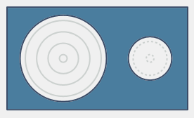
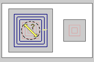
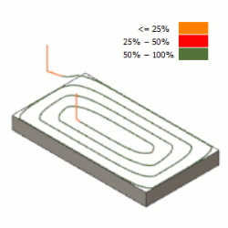
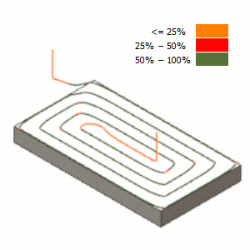
Tip: The images below show the results of the various combinations of filtering by type.
| Diagonal | Inscribed |
Circumscribed |
|
| Value |
|
|
|
| Contour |
|
|
|
| Region |
|
|
|
Processing
Sorting
-
By Area - machines an entire area of the part before
moving on to the next.
-
By Level - machines all areas of the part to the
current pass depth before beginning the next pass.
Intermediate Steps
- After
Last Depth Step - cuts all intermediate slices for the entire
model after the final depth step of the operation.

- After Each Depth Step - cuts the
intermediate slices for each depth step immediately after finishing
each depth.


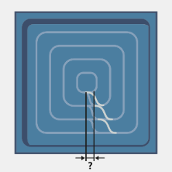
Break through amount
When using the Advanced Rough with Adaptive Roughing, the Break through amount becomes available. This will dictate how far the pocketing moves will continue on an open pocket before coming back to clean up the edges.
| Less | More |
|
|