


How it Works - Area Roughing for Impellers
Introduction
This topic describes the process used to create toolpath for impeller machining with or without a splitter. Because there are many variations in the design and shape of impellers, this topic provides an in-depth overview of the important steps to creating proper impeller machining.
How to Use Area Roughing
The first part of setting up Area Roughing is to create a base toolpath. The base path is a single pass around each blade using a swarf style toolpath (not the Swarf strategy). Area Roughing is then applied to the base toolpath to create roughing or finishing passes.
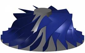
An example impeller geometry is shown next.
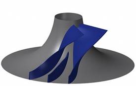
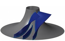
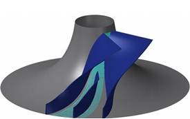
When creating the base path and area roughing, you only need to show the floor surface and one set of blades. This means two blades for impellers without a splitter and three blades for impellers with a splitter, as shown next. (Area Roughing requires at least two blade surfaces, that are used as Drive Surfaces, to create the toolpath between.)
The base toolpath is then applied to the blades using the following steps.
Machining Strategy
- Apply a Multiaxis Parallel to Surface
feature to create the base path. (You may be able to use other multiaxis
machining strategies such as Morph Between Two Curves.)
- Select the floor (gray) surface
as the Single Edge surface.
- Select the blades (blue surfaces)
as the Drive Surfaces.
- Select the floor (gray) surface
as the Single Edge surface.
- Set the Area Type to Determined by
Number of Cuts, and set the Number of Cuts to 1.000.
- You may need to apply a Margin to create a path in which the tool is tangent to both the floor and blade surfaces.
Tilting Strategy
- Apply the tilting strategy Tilted
Relative to Cutting Direction or Tilted Relative to Impeller Machining
Layer.
- When using Titled Relative to
Cutting Direction, set the Tilt Angle at Side of Cutting Direction
to 90.00 degrees (as a starting point). This value may need to
be reduced by a few degrees.
- When using Tilted Relative to Machining Layer, you must select two or three Tilt Lines.
- Select a tilt line at the lower edge and the upper edge of the blades.
- If there is a splitter, select a tilt line at the upper edge of the splitter blade.
- Select a tilt line at the lower edge and the upper edge of the blades.
- When using Titled Relative to
Cutting Direction, set the Tilt Angle at Side of Cutting Direction
to 90.00 degrees (as a starting point). This value may need to
be reduced by a few degrees.
Gouge Check
- Apply a gouge check using Tilting Tool Away with Max Angle.
This tilts the tool away from the drive surfaces.
- Select Use Side Tilt Angle.
- Select the Drive Surfaces check box.
- Select Use Side Tilt Angle.
- Apply a gouge check using Retract Tool Along Tool Axis. This
moves the tool up away from the floor or single edge surface.
- Select the Check Surfaces check box.
Assign the floor surface (the same used for the Single Edge surface) as the Check Surface.
- Select the Check Surfaces check box.
Toolpath Result
After defining the parameters explained previously, the resulting toolpath should look similar to the following.
Apply Area Roughing
Once the base toolpath is properly defined, you can then apply Area Rouging to create roughing or finishing paths.
- In the Roughing tab of the Multiaxis Wizard, select the Area Roughing check box to turn on the option. When you compute the toolpath, the result is similar to the following.
Related Topics
View Area Roughing