


 Patterns and Parameters
Introduction
This topic will explain the Patterns and Parameters page of the Lathe Rough operation and all the options found in it. This topic will also provide a link to the next topic.
The Patterns and Parameters page
The Patterns and Parameters page allows you to control the cutting pattern, its sorting, and compensation, while also providing options to adjust the depth of cut, allowance, overlap on passes, corner type (rolling over corners or not), and trimming the toolpath to match the stock size and shape.
 Patterns
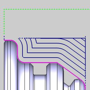
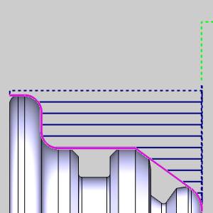
Pattern
The Pattern allows you to select how the passes are laid down.
![]() Standard - Each
pass will be parallel to the center of rotation.
Standard - Each
pass will be parallel to the center of rotation.
![]() Offset - Each pass
will be an offset copy of the selected geometry trimmed to the feature
constraints.
Offset - Each pass
will be an offset copy of the selected geometry trimmed to the feature
constraints.
| Standard | Offset |
|
|
|
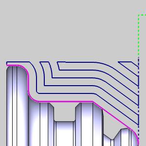
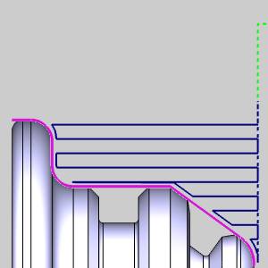
Sorting
Sorting allows you to select how the passes link to the following pass.
![]() Standard - defines
a one-way cutting pattern with retracts between each cut.
Standard - defines
a one-way cutting pattern with retracts between each cut.
![]() Zig Zag - defines
a two-way or alternating cutting pattern.
Zig Zag - defines
a two-way or alternating cutting pattern.
In the table below you can see how these sorting options affect the selected patterns.
| Standard Pattern | |
|
With Standard Sorting |
With Zig Zag Sorting |
|
|
|
| Offset Pattern | |
| With Standard Sorting | With Zig Zag Sorting |
|
|
|
Compensation
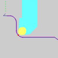
Each tool has a theoretical point placed on it as seen in red in the animation below. In the case of tools with a radius of any size, this point is not actually on the tool, but on the horizontal and vertical intersections of the radius. It is this point that the toolpath plots out. When compensation is used, it is designed to place the actual tool and not just its theoretical point on the geometry. This can be accomplished with System Compensation, Machine Compensation, or a combination of the two.
-
System Compensation
This specifies whether or not the system compensates for the insert geometry and the tool nose radius.
-
Off - the selected geometry is used as the program path; Machine Compensation should be used.
-
On with Collision Detection - the system compensates for the tool nose radius and the insert geometry and avoids any detected collisions.
 Use Tool Holder - no collision check is done on the holder.
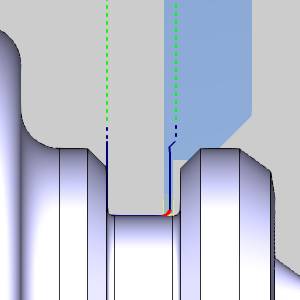
 Use Tool Holder - a collision check is done on the holder, and the toolpath is adjusted to ensure the tool holder does not collide with the geometry.
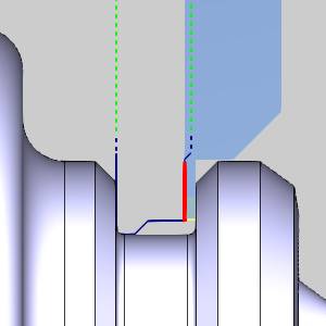
-
On without Collision Detection - the system compensates for the tool nose radius and the insert geometry without checking for collisions.
| System Compensation: | |||
|
Theoretical Point |
Off |
On with Collision Detection |
On without Collision Detection |
|
|
|
|
|
-
Machine Compensation
Outputs the necessary codes to allow for the user to enter compensation data at the machine. When this is done, the machine will alter the path based on the data entered at the machine. This can even be used in combination with System Compensation in order to compensate for tool wear or other unforeseen variables.
Parameters
Parameters
The parameters section give you the ability to adjust the depth of cut and the allowances used.
Depth of Cut - sets the spacing between toolpath passes.
![]() Rough Allowance -
Selecting this option will create a pass before the final
pass to act as a semi-finish. The spacing of the semi-finish pass will
be dictated by the values entered in the Z and X boxes.
Rough Allowance -
Selecting this option will create a pass before the final
pass to act as a semi-finish. The spacing of the semi-finish pass will
be dictated by the values entered in the Z and X boxes.
Z
- sets the amount left in the Z direction for the semi-finish.
X
- sets the amount left in the X direction for the semi-finish.
Finish Allowance
- will allow you to leave material on the workpiece to be handled
by the finishing pass. Setting values for the Finish Allowance will leave
the last pass of this operation offset from the selected geometry by the
amount entered in the available Z and X boxes.
Z
- sets the amount left in the Z direction for the finish.
X - sets the amount left in the X direction for the finish.
|
No Allowance |
Finish Allowance |
Rough & Finish |
|
|
|
|
|
|
|
|
|
No Allowance Simulation |
Finish Allowance Simulation |
Rough & Finish Simulation |
|
|
|
|
|
|
|
|
|
*Steps can also be eliminated with the Overlap options below. |
||
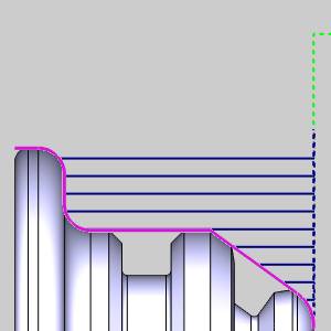
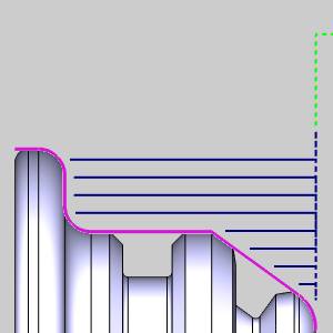
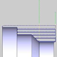
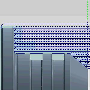
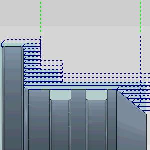
Overlap
The Overlap options allow you to create an additional move prior to the link to the next pass. This link will track back up the geometry in order to eliminate stair steps as seen in the images above. Overlap is controlled with either, To Previous Cut, No Overlap, or Custom Distance.
![]() To Previous Cut - automatically
tracks back up the geometry the distance of the selected depth of cut.
To Previous Cut - automatically
tracks back up the geometry the distance of the selected depth of cut.
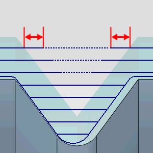
![]() No Overlap - does not track back
up the geometry at all.
No Overlap - does not track back
up the geometry at all.
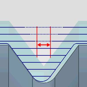
![]() Custom Distance - Allows you to
enter a custom distance value. This value is a vertical distance. Entering
the same value that has been entered for the depth of cut will track back
to the last cut exactly.
Custom Distance - Allows you to
enter a custom distance value. This value is a vertical distance. Entering
the same value that has been entered for the depth of cut will track back
to the last cut exactly.
Chip Break
The option allows you to create minute retract moves, at user specified intervals, to aid in chip breaking.
![]() Chip Break... - With this option cleared, the toolpath will not include chip break moves.
Chip Break... - With this option cleared, the toolpath will not include chip break moves.
![]() Chip Break... -
With this option selected, the toolpath will include chip break moves that can be modified in the Chip Break dialog. Click the Chip Break button to enter the dialog.
Chip Break... -
With this option selected, the toolpath will include chip break moves that can be modified in the Chip Break dialog. Click the Chip Break button to enter the dialog.
|
|
|
|

|
Options
This group allows you to determine how the intervals between retracts should be defined.
 Length of cut - The retracts are determined by the amount of space between them.
  Time - The retracts are determined by the amount of time between them.
- Length of chip - The retracts are determined by the amount of material being removed between them.
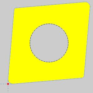
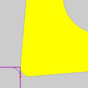
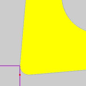
Corner Type
This section gives you a way to create sharp corners when moving through outside angles and corners. When system compensation is being used, the toolpath adjusts to keep the specified geometry of the tool in contact with the geometry. In the case of outside angles and corners, this causes a radius in the toolpath as the tool rounds over the geometry.
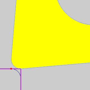
![]() Round - keeps the specified tool
geometry in contact with the geometry at all times.
Round - keeps the specified tool
geometry in contact with the geometry at all times.
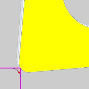
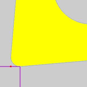
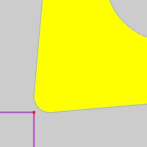
![]() Sharp - allows the tool to move
off the geometry in order to line up with the next move on the following
entity. This method eliminates the rounding over of the tool.
Sharp - allows the tool to move
off the geometry in order to line up with the next move on the following
entity. This method eliminates the rounding over of the tool.
|
Theoretical Point on Tool |
||
|
|
||
|
|
||
|
Rounded Corner |
||
|
|
|
|
|
|
|
|
|
Sharp Corner |
||
|
|
|
|
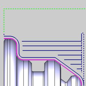
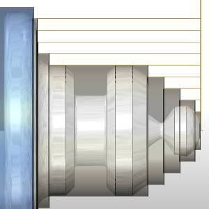
Bounds
The Bounds section give you the ability to trim the toolpath to the bounds set by the Operation Stock.
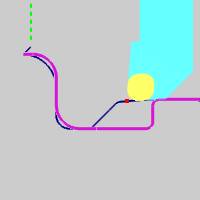
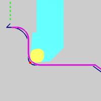
![]() Trim to Stock - With this option cleared, the toolpath will not be trimmed.
Trim to Stock - With this option cleared, the toolpath will not be trimmed.
![]() Trim to Stock -
With this option selected, the toolpath that extends beyond
the Operation Stock will be trimmed away.
Trim to Stock -
With this option selected, the toolpath that extends beyond
the Operation Stock will be trimmed away.
|
|
|
|
|
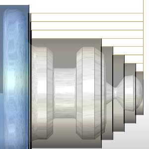
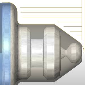
Extension - When trimming causes gaps in the toolpath, Extension closes the gap from each side by the amount entered. This is done to create a lead out of, and back into the material.
Maximum Gap - sets the limit on the area to feed across when no stock is detected.
Next Topic
Once the Parameters have been set, click Next >> to continue to the Rapids page.