


 Patterns and Parameters
Introduction
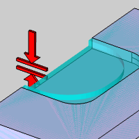
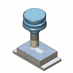
This topic explains the options found in the Patterns and Parameters page of the Pocket operation found in the Mill 2 Axis Wizard, and will provide links to related topics.
The Patterns and Parameters page
 Patterns
Patterns
-
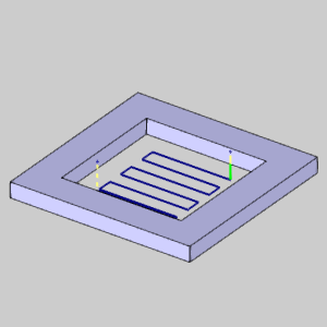
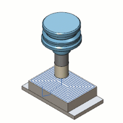
 Standard Pocket - creates a pocket with the specified patten. Standard pockets do not support open pockets.
- Parallel - creates a pattern
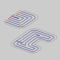
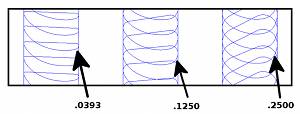
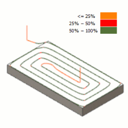
of parallel cuts where the tool feeds in both directions. With this pattern, you can select either No Profile, Profile After, or Profile Before, from the Final Contour group.
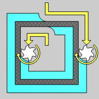
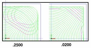
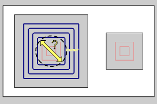
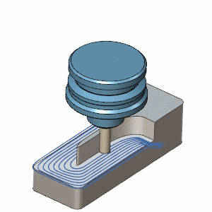
 Offset Pocket Out - creates a
pocket pattern which continually offsets the inner shape of the pocket and
creates the toolpath from the inside-out.
Offset Pocket Out - creates a
pocket pattern which continually offsets the inner shape of the pocket and
creates the toolpath from the inside-out.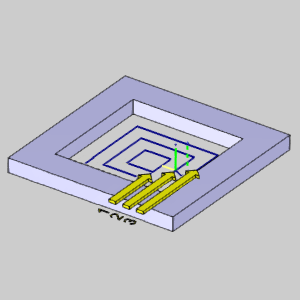
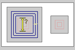
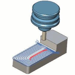
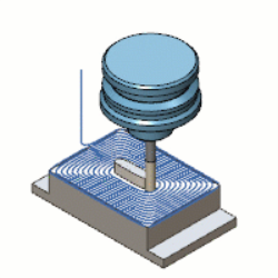
- Offset Pocket In - creates a
pocket pattern which continually offsets the outer shape of the pocket and
creates the toolpath from the outside-in.

-
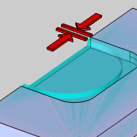
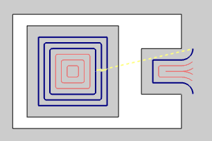
Advanced Pocket - creates a pocket with the specified patten. Advanced pockets are able to support open pockets. See the Open Pocket Example for more information.
- Parallel - creates a pattern
of parallel cuts where the tool feeds in a single direction. With this pattern, you can select either No Profile, or Profile After, from the Final Contour group.

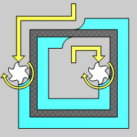
- Offset Pocket Out - creates a
pocket pattern which continually offsets the inner shape of the pocket and
creates the toolpath from the inside-out.
- Offset Pocket In - creates a
pocket pattern which continually offsets the outer shape of the pocket and
creates the toolpath from the outside-in. This option is different in that the first cut, which is against the wall of the pocket is skipped until the rest of the pocket is cleared out.
Standard Pocket Advanced Pocket 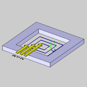
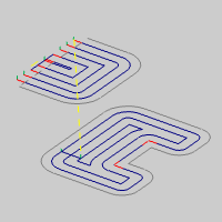
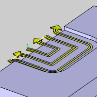
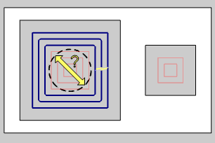
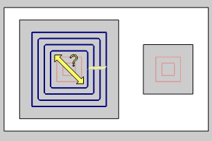
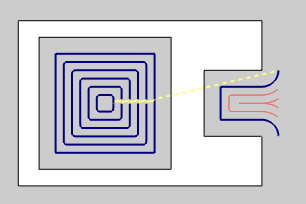
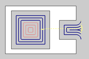
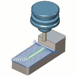
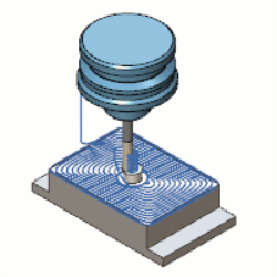
- Morph Spiral - creates a pocket pattern which combines a spiral and the offset shape of the pocket in order to eliminate linking moves. A morph is only applied in situations creating a closed contour. Open pockets will not always be able to utilize the morph pattern.
Standard Offset Morph Spiral 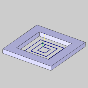
- Adaptive Roughing - creates a high-speed machining operation with automatic
tool engagement settings. When this option is selected, the Minimal Curvature
Radius is added to the Parameters group in this dialog box. In addition,
the Link Clearance is added to the Finish group in the Parameters page
of the wizard.
-
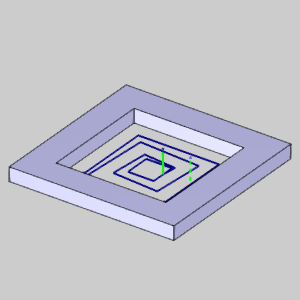
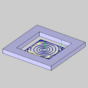
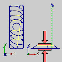
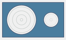
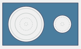
Use Spiral for Circular Pockets - Spiral pockets give the user the ability to create spiral toolpath instead of the standard offset toolpath for circular pockets. This option is not available when using the Morph Spiral, or Adaptive Roughing patterns.
 Select the check
box to a override the previously selected pattern in favor of a spiral
pocketing method on circular pockets.
Select the check
box to a override the previously selected pattern in favor of a spiral
pocketing method on circular pockets.  While the check box
remains unselected, the currently selected pattern will be applied
to all geometry, including circles.
While the check box
remains unselected, the currently selected pattern will be applied
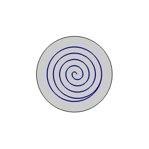
to all geometry, including circles. Offset
Spiral 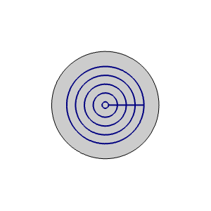
Final Contour - This group becomes available when the Parallel pattern is selected.
-
No Profile - No finish pass is calculated.
-
Profile After - A finish pass is added to remove the material from
the pocket after the pattern is applied.
-
Profile Before - A finish pass is added to remove the material
from the pocket before the pattern is applied. This option is not available when using the Advanced Pocket.
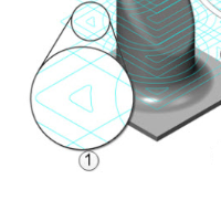
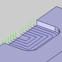
![]() Sharp Corner - This group becomes available when the Offset patterns are selected for Advanced Pockets.
Sharp Corner - This group becomes available when the Offset patterns are selected for Advanced Pockets.

|
|
-
Open Convex Corners Only - applies the Sharp Corners only to the open areas of the pockets. This can be helpful to avoid roll overs which may interfere with nearby part walls which should not be contacted with the tool.
-
All Convex Corners - applies Sharp Corners to all areas of the pocket, whether opened or closed.
Cut Direction
These options are only available when Offset Pocket In or Offset Pocket Out is selected.
- One Way (Advanced
Pocket)
Select the check box to define a one-way machining for the Advanced Pocket.
This enables the Climb Mill and
Conventional Mill cutting options.
- Climb Mill - the tool travels
in a counter clockwise direction along the inside shapes of the model
and travels in a clockwise direction along the outside edges of the
model.
- Conventional Mill- the tool travel in a clockwise direction along the outside edges of the model.
Clear the check box to use an offset pocketing strategy. One Way One Way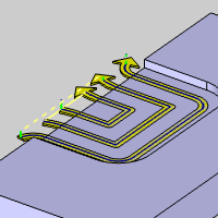
Rest Roughing
-
Rest Roughing
Rest Roughing-
With this check box cleared, the pocket will be handled normally. Rest Roughing - When the
Advanced Pocket pattern is selected, Rest Roughing calculates the
toolpath to remove all the non-machined areas remaining from the previous
roughing tool. It machines only those areas that are left behind by
the (larger) previous tool. In Rest Roughing toolpaths you normally
use a smaller step down (as the cutter size reduces) than the cutter
used for the previous roughing toolpath. Rest Roughing Rest Roughing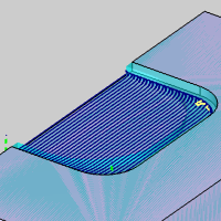
- Use Previous Operation
Select the check box to have the system automatically set the Rest Roughing
parameters using the tool parameters of a roughing operation that is previous
to this operation in the feature. Clear the check box to manually enter the tool parameters of the previous
roughing operation.
Clear the check box to manually enter the tool parameters of the previous
roughing operation.- Previous
Tool Diameter - set this to the
diameter of the previous tool used to rough the part. This value must
be larger than the tool being used for the rest roughing operation.
- Previous
Tool Corner Radius - set this to
the corner radius of the previous tool used to rough the part.
- Previous
Allowance XYZ - set this to the amount of side allowance used
for the previous roughing operation.
- Previous
Tool Diameter - set this to the
diameter of the previous tool used to rough the part. This value must
be larger than the tool being used for the rest roughing operation.
- Use Previous Operation
Parameters
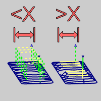
- Lace Angle - sets the angular direction
of the toolpath from the X-axis of the machining origin when using
the Parallel pattern.
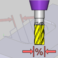
- Stepover
% - Sets the distance between passes as a percentage of the tool diameter. Updating this field automatically updates the absolute value.
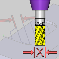
- Stepover - Sets the distance between passes using an absolute value. Updating this field automatically updates the percentage.
Note: The following two parameters are only available when using the Advanced Pocket with Adaptive Roughing, without using the Oneway cut direction option.
- Max
Stepover % (Climb) - sets the maximum stepover as a percentage
of the tool for zigzag cutting. When Max Stepover % (Conventional)
is selected, this is only applied to the climb milling portion of
the toolpath.
- Max
Stepover (Climb) - sets the maximum stepover as an absolute value for zigzag cutting. When Max Stepover % (Conventional)
is selected, this is only applied to the climb milling portion of
the toolpath.
- Max Stepover %
(Conventional)
Select the check box to specify that maximum stepover as a percentage
of the tool for conventional milling.
Clear the check box when not specifying the conventional stepover for
conventional milling. - Max Stepover
(Conventional) - specifies a maximum stepover as an absolute value for conventional milling.
Note: The following parameter is only available when using the Advanced Pocket with Adaptive Roughing.
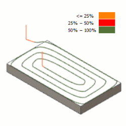
- Minimal Curvature Radius - determines the smallest radius used in the toolpath motion. This value must be greater than zero, but be aware that if you set this value too high, no toolpath is created. This parameter is useful, for example, to determine how far into a corner the toolpath can reach.
The following parameter is only available when using the Advanced Pocket with Parallel, and without using the Oneway cut direction.
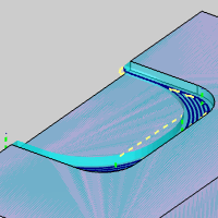
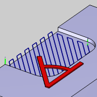
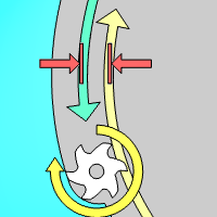
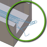
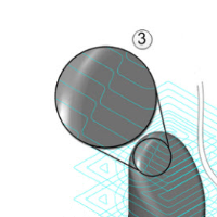
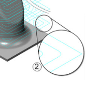
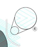
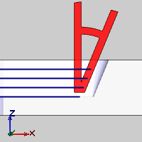
![]() Select the check box to apply a tangent move to the link connection. The specified radius can be anywhere from 0, to half the step over. Notice in the animation below, arcs of a specified size can be applied to the link move.
Select the check box to apply a tangent move to the link connection. The specified radius can be anywhere from 0, to half the step over. Notice in the animation below, arcs of a specified size can be applied to the link move.
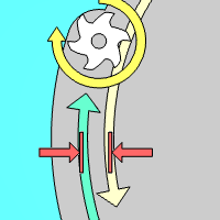
![]() Clear the check box when not utilizing a smooth connection.
Clear the check box when not utilizing a smooth connection.
Note: The Smooth Connections option is only available when an Advanced Pocket / Parallel Pattern is used, and One Way Cut Direction is turned off.
Parameters
Finish
- Side Allowance -
sets the amount of material that remains on the walls for finishing.
The material is removed on the finish pass.
- Bottom Allowance -
sets the amount of material that remains on the floor for finishing.
The material is removed on the finish pass.
- Link Clearance - When using the Advanced Pocket with Adaptive Roughing, the Link Clearance becomes available. This will allow you to set a height to the linking moves used in the adaptive moves.
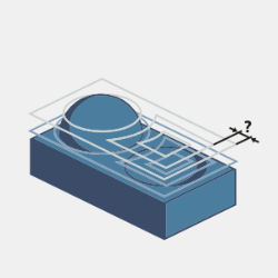
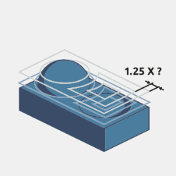
- Retract Threshold (x Tool Diameter) - When using the Advanced Pocket with Adaptive Roughing, the Retract Threshold becomes available. This allows you to specify a maximum length link before a Rapid Retract for Large Gaps should be utilized.
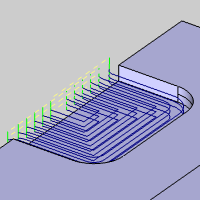
- Break through amount - When using the Advanced Pocket with Adaptive Roughing, the Break through amount becomes available. This will dictate how far the pocketing moves will continue on an open pocket before coming back to clean up the edges.
Other
Advanced - launches the Roughing Advanced dialog. The content of this dialog will vary depending on the options used.
Depth
Method
-
Single Step - the Total
Depth value is processed in one pass.
-
Multiple Steps - the Total
Depth and Depth of Cut values are used to generate the number of equal
cuts used to process the profile operation. This enables the Depth Step options.
Depth Step
When Multiple Steps are selected in the Method group, the Depth Step options become available.
-
Even Depths - the total
depth is processed in even depths of cut. If you type a value that
is not an equal division of the total depth, the value is automatically
calculated to the closest value.
-
Defined Depths - uses the
Depth of Cut value to define the depth of cut. If the value is not divisible by the Total Depth, the last cut will be the depth needed to achieve the proper Total Depth.
-
Custom Depths - allows you to set a specific number of cuts, each at a specific depth. Once selected, click Add and define the depth at which the cut should be made. Highlight and Delete cuts as necessary.
Taper/Draft Angle Option
When the Advanced Pocket is being used, this section allows for the creation of tapered pockets.
- Angle - sets the degree of taper used on the creation of the pocket walls. The value must be less than 90 degrees and greater than, or equal to, 0.
-
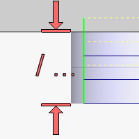
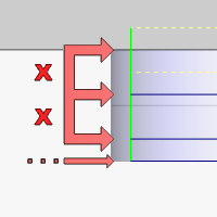
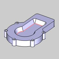
Geometry at Top - The geometry defines the top edge of the tapered pocket, with the taper extending downward.
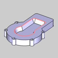
-
Geometry at Bottom - The geometry defines the bottom edge of the tapered pocket, with the taper extending upward.
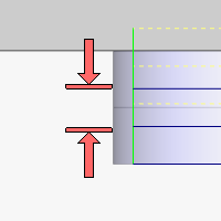
- Total
Depth - displays the depth (set in the Feature settings)
of the material removed by the feature.
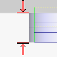
- Depth
of Cut - for the Multiple Steps option, this is the depth at
which each equal pass is processed. This value may be different
than entered because the value of the Number of Cuts must be a whole
number and the depth of each pass is the Total Depth divided by the
Number of Cuts.
- Number
of Cuts - for the Even Depth option, this value is calculated
by the system using the Depth of Cut value.
Related Topics
Clicking Next> > takes
you to the next page of the Mill 2 Axis Wizard. To move to the corresponding
topic, click the appropriate link below.
The Profile Rough Parameters
page
The Profile Finish Leads page
The Pocket Leads page
The Facing Leads page
The Engrave Advanced Feedrates page
The Chamfer Mill Parameters
page
The Plunge Rough Parameters
page
The Corner Rounding Parameters page
The Open Pocket Example.