|
This section explains how to select
geometry for Drill, Tap, Counterbore, and Thread features.
This information applies to standard hole drilling, multiaxis
drilling, and cross drilling.
Geometry Selection
To access the Selection Manager for
hole geometry, do one of the following:
- In
the Hole Wizard, click Select
Geometry.
- Under
a Hole feature in the CAM Tree, right-click
Geometry and click Re/Select.
The Hole Geometry Picking options
display in the Property Manager.
Select the Drilling Type
The first part of using the Selection
Manager is to select the type of drilling you are performing:
Standard, Multiaxis, or Cross Drill (for Mill Turn only). The
software automatically filters the geometry that you select to
only include holes (tool orientations) that can be drilled using
the selected type.
Tip: The
drilling type that you select during hole geometry selection determines
the type of feature that you are creating: Standard, Multiaxis,
or Cross Drilling. The geometry that you select is automatically
filtered to remove orientations that do not apply to the selected
drilling type and machining origin coordinate system. [The filtering
happens when you confirm (OK) the selection.]
Standard Drill
Standard drilling, the default drilling
type, is used when the tool orientation to drill the holes is
parallel to the main spindle direction, usually the Z-axis. This
includes face drilling for Mill Turn jobs. Standard drilling may
also be used with index systems, for example, with 3x2 machining
on a 5-axis machine where you index to a plane and then perform
3-axis machining (although multiaxis drilling eliminates the need
to create index systems).
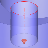
Mill or Mill Turn
Standard Drilling
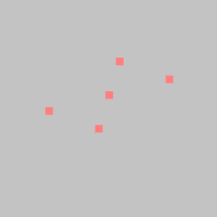
The following images show toolpath
examples of standard drilling for both Mill and Mill Turn jobs.
|
Mill Standard
Drilling
|
Mill Turn Standard
Drilling
|
|
|
Multiaxis Drill
Multiaxis drilling is used for multiaxis
machining (more than three axes), in which the tool orientation
may or may not be parallel to the main spindle direction. This
drilling type is also used for Mill Turn jobs, for example, when
drilling holes on the circumference where the tool orientation
does not point to (or cross) the rotation axis of the part (usually
the Z-axis).
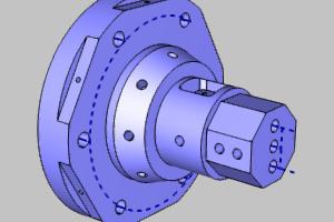
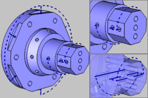
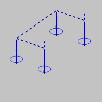
Mill or Mill Turn
Multiaxis Drilling
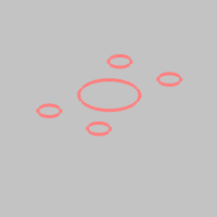
The following images show some example
multiaxis toolpath. Note that Multiaxis drilling can also perform
standard drilling.
|
Mill
Multiaxis Drilling
|
Mill
Turn Multiaxis Drilling
|
|
|
Cross Drill
Cross drilling is only available
for Mill Turn jobs, which may be called diameter or radial drilling.
This drilling type is used when the tool orientation points directly
to, or crosses, the rotation axis of the part, usually the Z-axis.
Note that the tool orientation must also be perpendicular (at
a right angle) to the rotation axis. On the physical machine,
the tool orientation for cross drill holes is parallel to the
X-axis.
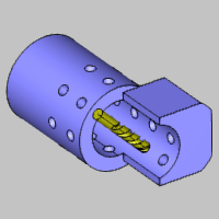
Mill Turn Cross
Drilling
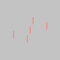
The following images show example
cross drilling toolpath. Note that cross drilling does not require
Y-axis capabilities. Drill holes that require Y-axis movement
are not considered cross (radial) drilling and are handled using
Multiaxis drilling.
|
Mill Turn Cross
Drilling
|
|
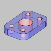
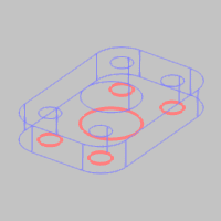
Supported Geometry Types
When selecting geometry for drilling
features, you can select whole
solids, points, arcs, lines, surface edges, or
cylindrical surfaces. All drilling types support all of these
geometry selections, with one exception that points cannot
be selected for multiaxis drilling.
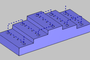
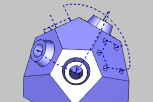
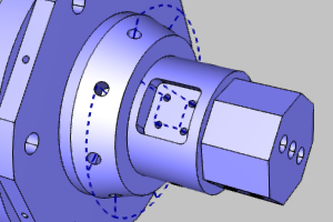
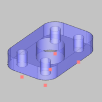
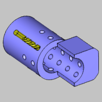
Drill Holes Example
Part
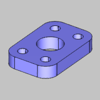
Supported Geometry
Selections
The following images show all supported
geometry selections that can be used to for the example part.
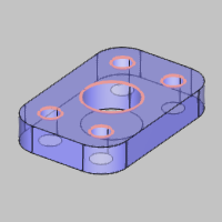
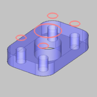
|
Surface
Edges (Top or Bottom)
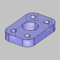
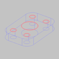
|
Cylindrical
Surfaces
|
|
|
|
Important Notes About Geometry Selection
Benefits of Cylindrical
Surfaces
Selecting cylindrical surfaces allows
the software to automatically set the diameter, top of feature,
and the feature depth for you. You must manually set one or more
of these values when using any other geometry type.
Benefits of Lines
Selecting lines allows the software
to automatically set the top of feature and the feature depth
for you. Note that you must type the diameter value in the wizard.
Points, Arcs,
or Surface Edges
Depending on the Z-axis location
of the geometry and the settings that you define, the software
may automatically set the diameter, top of feature, or feature
depth, but not all of them. Be sure to properly set (or confirm)
all of these parameters when using these geometry types.
Multiaxis Drilling
Points cannot
be selected for multiaxis drilling (as no direction can be determined
from a point).
Selecting
Whole Bodies
When
using the Select Whole Bodies option, the software automatically
creates features for all holes (or radii) found in the model.
This may result in more features than desired, but you can simply
delete the extra features from the CAM tree after finishing the
wizard. Note that you can use the Options group to limit the hole
diameters for which the software creates features.
Geometry Filtering
The software automatically filters
the geometry selections you make in a few ways. First, the software
attempts to remove all extra geometry, for example, duplicates
or concentric entities. Second, the software filters the selections
you make, based on the drilling type and hole/tool orientation,
to remove holes with orientations that are incorrect for the selected
drilling type.
Important: If
you find that the geometry you select for drill holes is being
removed by the software, confirm that you are selecting the appropriate
geometry for the drilling type. For example, with standard drilling,
a hole that isn't parallel to the Z-axis is removed because it
would require multiaxis drilling.
Hole
Selection Parameters
The parameters that display in the
Selection Manager change slightly for each drilling type as explained
next.
Standard Drill
After selecting Standard Drill, the
following options become available.
Point or Arc Usage
These options determine how the software
calculates the toolpath when selecting points, arcs, or surface
edges for hole geometry.
Multiaxis
After selecting Multiaxis, the following
options become available.
Arc Usage
These options determine how the software
calculates the toolpath when selecting arcs or surface edges for
hole geometry.
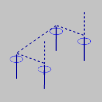
Drilling Direction
and Removing Individual Holes
When selecting geometry for multiaxis,
each hole contains a drilling direction, which is indicated by
an arrow in the graphics area. You must properly define the direction
for each hole using the Geometry list and the following options.
Hole
Direction
Under
Hole Direction, the Holes list is provided to allow you to reverse
the direction of each selected hole. To reverse the direction
of one or more holes, select items in the Holes list and use the
following buttons.
-
 Reverse - is used to
reverse the drilling direction of the holes that are selected
in the Geometry list.
Reverse - is used to
reverse the drilling direction of the holes that are selected
in the Geometry list.
-
 Reverse All - is used
to reverse the drilling direction of all holes in the
Geometry list.
Reverse All - is used
to reverse the drilling direction of all holes in the
Geometry list.
-
 Delete - removes
all currently selected holes from the holes list. This
is helpful, for example, when selecting CAD features or
using Select Whole Bodies and you want to remove individual
holes from the selection, but not the entire selection. Delete - removes
all currently selected holes from the holes list. This
is helpful, for example, when selecting CAD features or
using Select Whole Bodies and you want to remove individual
holes from the selection, but not the entire selection.
Cross Drill
After selecting Cross Drill, the
following options become available.
Rotation Axis
This option must be set to the appropriate
rotation axis of the part using one of the following options.
-
Z Axis - is used when
the rotation axis of the part is the Z-axis of the machine
setup (machining origin).
-
X Axis - is used when
the rotation axis of the part is the X-axis of the machine
setup (machining origin).
-
Y Axis - is used when
the rotation axis of the part is the Y-axis of the machine
setup (machining origin).
-
Pick Axis - allows you
to define a custom rotation axis for the part by selecting
geometry. After selecting Pick Axis, a selection box displays
in the Rotation Axis group. Click in the box, and then
select a line from the graphics area to define the rotation
axis. The name of the selected entity displays in the
box.
ID Drill
 Select the check
box when the drilling direction is outward or from the inside
of the part to the outside. Select the check
box when the drilling direction is outward or from the inside
of the part to the outside.
 Clear the check
box when the drilling direction is inward or from the outside
of the part to the inside. Clear the check
box when the drilling direction is inward or from the outside
of the part to the inside.
The Geometry List
Selecting and Removing Geometry
The entities that you select in the
graphics area or Feature Manager
Design Tree display in the Geometry list. To remove
geometry, right-click in the Geometry list to open a shortcut
menu with the following options.
Tip: You can also
remove geometry selections by clicking entities in the graphics
area, but note that this method clears the current selections
in the Geometry list.
Selecting
Whole Solids
-
Select Whole Bodies
Select the check box to enable whole body selection. When
you click a part model, the entire model is selected. Single
entity selection is disabled. When using the Select Whole
Bodies option, the software automatically creates features
for all holes (or radii) found in the model. This may result
in more features than desired, but you can simply delete the
extra features from the CAM tree after finishing the wizard.
Note that you can use the Options group to limit the hole
diameters for which the software creates features.
Clear
the check box to use standard single entity picking. This
allows you to select single sketches, edges, surfaces, or
CAD features.
Geometry Highlighting
You can click an entity name in the
Geometry list to display that entity in the graphics area using
the system highlight color.
Selecting Multiple Entities in the
Geometry List
The Geometry list allows for multiple
selections using standard controls as follows.
-
Click
an entity name in the list to select it.
-
Hold
down the Ctrl
key and click an entity to add it to or remove it from the
selection.
-
After
selecting one entity, hold the Shift
key and click another entity to select all entities in between
the first and second selections.
Parameters
-
Rapid Plane -
sets the rapid height for the feature as an incremental value
from the Top of Feature. The rapid plane determines the safe
rapid distance used within an operation (clearance plane is
used between operations). This defines the default value used
in the CAM Wizard.
-
Tolerance -
is a selection tolerance that is used in the feature detection
based on the type of selections made. For most scenarios,
you should not have to change this value.
Options
The
Options group allows you to set a range of holes sizes (diameter)
considered when selecting geometry. No features are created for
all selected hole diameters outside of this range.
|
 Geometry Selection
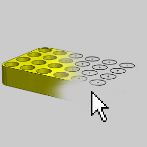
 ) to confirm the selection and
return to the wizard.
) to confirm the selection and
return to the wizard. Click
here to expand the section on the Hole Geometry Picking manager.
Click
here to expand the section on the Hole Geometry Picking manager.