Margins
Introduction
For use with Full, Start and End at Exact Edges or Determined by Number of Cuts, the cuts start or end at the exact edge of the drive face. The toolpath on the surface edge now has a defined position. With this position it is possible to define a certain margin from the surface edge for the first cut and the last cut.
The Dialog Box Parameters
-
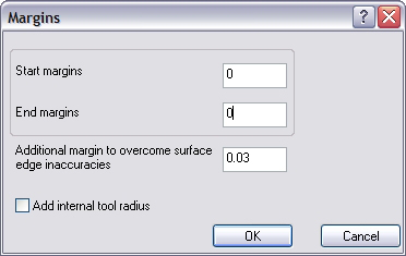
Start margins - sets the margin used at the first edge or curve.
-
End margins - sets the margin used at the last edge or curve.
-
Additional Margin to Overcome Surface Edge Inaccuracies - is used to help compensate for system tolerances. This value is added to the margin. If you set this option to one and the margin to four, then the toolpath is generated 5 units from the edge.
-
Add Internal Tool Radius
 Select the check box to add the tool radius value to the other margin
values.
Select the check box to add the tool radius value to the other margin
values.
![]() Clear the check box to turn off this option.
Clear the check box to turn off this option.
Margin Examples
-
Morph Between Two Curves
An example could be a turbine blade with two floor faces. Although you are using Morph Between Two Curves, there are enclosing floor faces on both sides. You don't want the tool to gouge these faces. When you set the Margin equal to the tool radius, the tool is kept that distance from floor faces so it doesn't gouge. Always use a Margin that is at least the same as the tool radius. The start margin is for the first curve, and the end margin is for the second curve.
-
Morph Between Two Surfaces
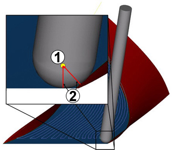
The area type has to be set to Full, Start and End at Exact Surface Edge because the distance between the margin and the first cut depends on the exact position of the surface edge. You see in the next image why it is so important. In this impeller example you have an inlaying edge. The toolpath has to fit in that edge to avoid a gouge. When you set a margin equal to the tool radius (1), the tool is kept that distance from floor face and blade face (2). Always use a Margin that is at least the same as the tool radius.
-
Parallel to Surface
An example could be two crossing faces, the drive face plunges through a check face. You don't want the tool to gouge so the machining must stop before the drive face plunges into the check face. When you set a margin equal to the tool radius, the tool is kept that distance from the check face. Always use a Margin that is at least the same as the tool radius.
-
Additional Margin to Overcome Surface Edge Inaccuracies
Toolpath strategies that use edge curves and surfaces can sometimes be fragmented since CAD systems provide the drive surfaces and the edge geometry only within a certain accuracy (tolerance). To start the toolpath at exactly zero distance from the edge geometry is problematic since the geometry can never be exactly aligned. For this reason an edge tolerance is used. The toolpath generated is at the distance of the Surface edge curve tolerance plus the Margin value entered. So, to create a toolpath at 5 units distance, you can keep the surface edge tolerance at 0.03 and enter a margin of 4.97.
-
Add Internal Tool Radius
For a pencil trace machining it is necessary to have at least the tool radius margin to the leading curve or surface. By activating this option the tool radius is added to the margin and the additional margin.