Assigning Lathe Tool Inserts
Introduction
BobCAM allows you to assign geometry to define custom lathe tool inserts for tools that can't be created using the provided insert types.
To Assign a Tool Insert
-
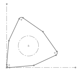
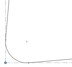
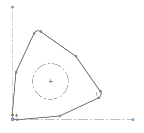
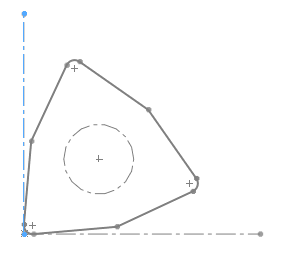
In the graphics area, draw the 2D shape of the insert.
At the position of the attachment point to
the tool holder, place a
Place a point at the theoretical tool point.
This point is normally tangent to the forward and bottom extents of the tool nose radius.
- Define the X-axis and Y-axis with the tool point at the origin.
-
To open the Tool Library, do one of the following.
-
-
Right-click
 CAM Defaults, and click
Tool Library:
CAM Defaults, and click
Tool Library: -
Right-click
 Turning Tools, and click
Tools.
Turning Tools, and click
Tools.
-
- You
can either select an existing tool and click Modify,
or if you are creating a new tool, click Add.
At the top of the dialog box, click Assign Tool Insert.
The Select Insert/Holder Geometry Manager displays. - Click to select the outer
geometry of the insert.
The selections display in the Selected Tool Insert/Holder Items box.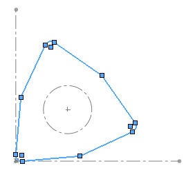
-
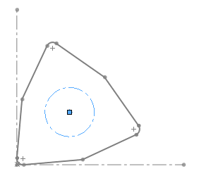
Click the Selected Tool Attachment Circle box, then click the corresponding sketch entity.
Note: The Tool Attachment Circle is only required if the insert is to be associated with a tool holder.
-
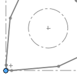
Click the Selected Tool Reference Point box, then click the corresponding sketch entity.
- Click the X-Axis
for Insert Geometry box, then click the corresponding sketch
entity.
-
Click the Y-Axis for Insert Geometry box, then click the corresponding sketch entity.
To finish assigning the tool insert, click OK.
OK.
At the bottom of the tool dialog box, click OK to save the new custom tool insert.