Advanced Options for Gouge Checking
Introduction
The Advanced Options for Gouge Checking provide additional options to help better accommodate certain situations.
Navigation
To access the Advanced Options for Gouge Checking dialog box:
- Click Advanced at the bottom of the Gouge Check tab.
Gouge Check Between Positions
-
Gouge Check Between Positions - the 5-axis sweep move from one position to the next position is checked for collisions with the drive and check surfaces. To create proper toolpaths and to avoid gouges, select this option.
-
 Select the check box to gouge check between positions.
 Clear the check box to
not gouge check between positions.
Clear the check box to
not gouge check between positions.
For flat surfaces, toolpath points are only generated at the edges. Because there are no points between the edges, the standard gouge check wouldn't show a gouge. When setting a Maximum distance value, this option may not be necessary.
Example
-
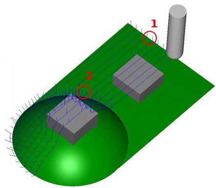
Gouge Check Between Positions
On the flat part of this example no toolpath points lie between the edges. The tool gouges with the grey check surface. On the round part, many toolpath points exist. For this part, the gouge checking works even without using Gouge Check Between Positions.
-
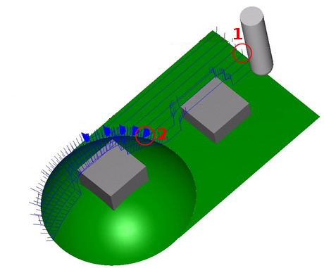
Gouge Check Between Positions
On the flat part of this example, no toolpath points lie between the edges. When usingGouge Check Between Positionsthe system finds the grey check surface and avoids the gouge. On the round part of this example, many toolpath points exists. Gouge checking works even without usingGouge Check Between Positions.
Extend Tool to Infinity
-
Extend Tool to Infinity - turns on and off the extension of tool geometry to infinity. It might be desirable to extend the last used portion of the tool with a cylinder to infinity. This will help the collision checking system to detect all collisions happening. For example, when using guide surfaces (such as a thin cylinder) and then retracting the tool to the actual part geometry defined as a check surface. If the total tool length (including holder and arbor) is not long enough, the collision checking system can find a collision free location for the tool between the thin cylinder and real part geometry. In this case, making the tool longer resolves the problem. When usingExtend Tool to Infinity, it is not necessary to change the tool length manually to a larger value.
Select this check
box to virtually extend the tool to infinity for gouge checking.
![]() Clear the check box to leave the tool at its actual size.
Clear the check box to leave the tool at its actual size.
Check Link Motions for Collisions
-
Check Link Motions for Collisions - is used to avoid collisions that happen during toolpath link moves. The software handles the gouge checking differently for the different link types. The system attempts to automatically create a gouge free toolpath. If a gouge free toolpath can't be accomplished, then some other settings need to be changed.
-
Select the check box to gouge check link movements.
Clear the check box to not gouge check link movements.
Check Link Motion Against Containment
-
Check Links Motion Against Containment - makes sure that direct, blend spline, or follow surface links stay within the containments, and when the toolpath has to cross-cut the containments, the links are replaced with the clearance area linking. Containment can be (1) the active containment (2D or silhouette) or (2) other curves (user defined).
Select this check
box to gouge check link movements to make sure they are within the proper
containment.
![]() Clear the check box to not gouge check
link movements within the proper containment.
Clear the check box to not gouge check
link movements within the proper containment.
Report Remaining Collisions
-
Report Remaining Collisions - the calculated toolpath is generated with a tolerance twice the user given value to help detect collisions between tool and holder pieces (as selected in the Gouge Check page) against all geometries (selected in the Gouge Check page) as drive surface or check surfaces. Note that generally speaking, collisions are not desired behavior and an explanation is given next as to why there can be remaining collisions to report after gouge checking has already been performed:
-
If collision control is turned off between positions, the toolpath calculation speed is increased, but remaining collisions can result.
-
When engraving or trimming, the tool tip is inside the surfaces which can result in remaining collisions.
-
When lead-in or lead-out distances are too small, or a rapid plane is too low, remaining collisions can result.
-
If the gouge check options are not set up properly remaining collision can result.
-
The tolerance used for gouge checking is the maximum tolerance used for all gouge checking strategies, except for ReportRemaining Collisions.
Select this check
box to use report remaining collisions.
![]() Clear this check
box to turn off report remaining collisions.
Clear this check
box to turn off report remaining collisions.
Check Tip Radius
-
Check Tip Radius - can be used with gouge check option Tilt Tool Away. This option deactivates gouge checking for the flute radius of a ball mill or bull mill.
-
Select the check box to gouge check the tool
tip radius. Clear
the check box to turn off gouge checking of the tool tip radius. This
is used for example, if you want to ignore a gouging tool tip for
a specific scenario.
Example
-
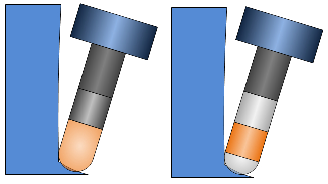
In the next image on the left the tool tilts away from the wall to avoid a collision with the holder. This forces the tool tip to gouge with the floor. Now the collision check would then try to tilt the tool away from the floor as well, but as you can see this is not possible. The contact point of the tool stays the same, in this case the tool would simply rotate around the contact point of tool and surface. The collision can't be solved. The result is a toolpath which is not collision free.
-
In the previous image on the right, you see that the flute is not checked for collisions. Now the toolpath is not collision free, but because there is now a solution, the calculation will not fail. The remaining collisions can be removed with an additional gouge check strategy.