Tilt Tool - Gouge Check Strategy
Introduction
The Tilt Tool gouge check strategy is designed to avoid collisions by tilting the tool instead of retracting. Depending on the tool tilting strategy (Tool Axis Will) selected in the Tool Axis Control page, the available options differ. All of the options are explained next. Again, not all options listed in this topic are applicable for all Tilting strategies.
Tilting Options
-
Use lead/lag angle - tilts the tool forward or backward relative to the cutting direction. Positive angles tilt the tool forward, and negative angles tilt the tool backward. The limits are from +/- 0.01 degrees to +/- 180 degrees. Click Parameters to set these values in the Parameters for Tilting Tool Away with Max. Angle dialog box. This is explained in the Parameters section of this topic.
-
Use side tilt angle - tilts the tool to the side relative to the cutting direction. Positive angles tilt the tool to the right, and negative angles tilt the tool to the left. The limits are from +/- 0.01 degrees to +/- 180 degrees. Click Parameters to set these values as explained in the Parameters section of this topic.
-
Automatic - is an automatic tilting calculation in which the software tilts the tool in any direction to handle the tool tilting used to avoid collisions based on the settings and preferences you define the Advanced Options for Automatic Titling dialog box.
Example
-
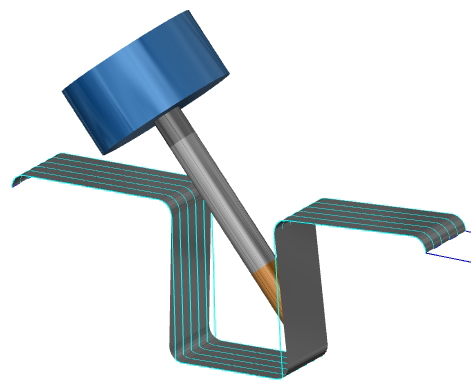
In this example the tool stays normal to the drive surface. The shape of the drive face forces the tool to gouge.
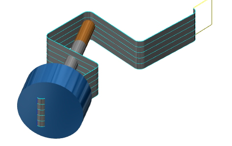
-
By using Use Lead/Lag Angle the tool tilts away from the collision.
Extra attention is required when using flat tools. When using an end mill, tilting forward or backward changes the contact point of the tool which can result in other collisions.
Parameters
The options, Use Lead/Lag Angle, Use Side Tilt Angle, and Change Fixed Tilt Angle are further controlled using the Parameters. Click Parameters to access these options as explained next.
-
Max. tilt angle - determines the maximum tilt angle forward to or left of the cutting direction depending on the gouge check setting (for lead/lag this is forward and for side tilt this is left). This value must be between 0 and 180 degrees.
-
Min. tilt angle - determines the minimum tilt angle backward from or right of the cutting direction depending on the gouge check setting (for lead/lag this is backward and for side tilt this is right). This value must be between -180 and 0 degrees.
-
Clearance Angle - protects against collisions with the drive face and the back end of the tool (non-cutting area). Click the link to view How it Works - Clearance Angle.
Smoothing
Smoothing is used to help eliminate unnecessary tool movements from a toolpath. To turn on smoothing, select the check box next to Smoothing. Next, click Smoothing to open the Side Tilt Angle dialog box. The available options are explained next.
Smoothing
-
Smooth tilt angles
-
Minimum - sets the minimum tilt angle for smoothing.
-
Maximum - sets the maximum tilt angle for smoothing.
-
Smooth rotary angles
-
Minimum - sets the minimum rotary angle for smoothing.
-
Maximum - sets the maximum rotary angle for smoothing.
-
Rotary axis - click the arrow to select the rotary axis used: X-axis, Y-axis, Z-axis, or User defined. WhenUser definedis selected, you can click
 to enter coordinate values, or
clickPick to select geometry.
to enter coordinate values, or
clickPick to select geometry.
-
Blending distance - when the check box is selected the other smoothing options become unavailable. The blending distance controls how far from a collision the tool begins to tilt in order to avoid that collision. Click the link to view How it Works - Smoothing. Clear the check box to turn off this option.