Emboss 2-Rail Sweep
Introduction
This topic will explain the Emboss 2-Rail Sweep, describe where to find it, the options found in it, and will provide links to related topics.
Emboss 2-Rail Sweep
The Emboss 2-Rail Sweep feature creates an emboss with one or more cross
sections swept along two rails. Generally, the two rails are drawn inside
the emboss stock that you create, and the cross section geometry can be
drawn anywhere in the XY plane
Navigation
To create a 2 Rail Sweep feature:
-
In the
 BobART tab, right-click
  Emboss
Model, and click Emboss2 Rail Sweep.
Emboss
Model, and click Emboss2 Rail Sweep.
The 2-Rail Sweep dialog box displays.
Parameters
Emboss Attributes
- Name- indicates the feature name that displays in the BobART tree.
By default, it is automatically named by the feature type and
number. Note that you cannot use the hyphen (-) character with
spaces around it, as this is reserved for the automatic naming
and will be removed. You can however use it without spaces, for
example, Emboss-Body).
- Color - opens the
Color dialog box. Select the desired color for the feature, and
click OK.
Emboss
- Scale Cross
Section Based on Width- To learn more, view the Emboss
2 Rail Sweep Leaf tutorial.
 Select the check box to have the entire cross-section geometry,
including the height, scaled to fit between the rails.
Select the check box to have the entire cross-section geometry,
including the height, scaled to fit between the rails.
 Clear the check box
to have the cross-section geometry width, excluding the height,
scaled to fit between the rails. This results in a model with
a height that is equal to the height of the selected cross section.
Clear the check box
to have the cross-section geometry width, excluding the height,
scaled to fit between the rails. This results in a model with
a height that is equal to the height of the selected cross section.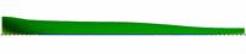
- Sync Rail Nodes - To learn more, view the Sync
Rail Nodes tutorial. For use when
both rails have an equal number of entities, select this check
box to force the cross sections to match at the end of each entity.
Note that the start point of each rail should use the same location
on each rail.
 When the check box is cleared
there is no effect on the embossed model.
When the check box is cleared
there is no effect on the embossed model.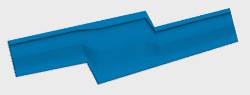
- Use 3D Rails - Select the check box to use rails that are not flat. This
allows the rails to extend outward from the surface of the stock
model.
 Clear the check box to automatically
flatten the 3D rails to the stock surface.
Clear the check box to automatically
flatten the 3D rails to the stock surface.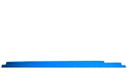
- Geometry List Box - is located below the Use 3D Rails check box, this box displays a list of the geometry associated with the operation. Click a geometry item to show a preview in the window below the Cross Section Spacing options.
Application Type
These options are explained in more detail in the Application
Types help topic.
- Add - Builds up on top of whatever is already there.
- Subtract - Pushes down into whatever is already there.
- Merge High - Builds up independent of whatever is already there and intersects as needed.
- Merge Low - Builds up in place of whatever is already there.
Transition Type
Blends the shape of one cross section into the shape of the other. These options apply when three or more cross sections are in use. The Transition Types are for use with three
or more cross sections. There are three transition types available:
- Linear - creates a linear blend between the
cross sections.
- Local Smooth - creates a smooth blend from one cross section to the next to make a smoother appearing transition.
- Global Smooth -creates a smooth blend between
all cross sections in
a manner similar to the Local Smooth
transition type. This creates a smoother transition across the entire
model.
Transition Examples
A model is used next in order to better show the difference between the transition types. The three cross section entities used in this example are shown next.
| First Cross Section | Second Cross Section | Third Cross Section |
|
|
|
|
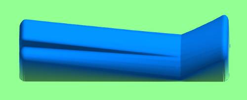
Sweeps generated with the previous entities using the three transition types are shown next.
| Linear |
|
|
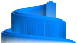
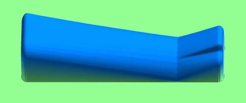
| Local Smooth |
|
|
| Global Smooth |
|
|
The three previous images were all created using the Scale Cross Section Based on Width option which resulted in a significant height change between cross sections. The first cross-section width is half of the distance between rails, so it is scaled 200% to fit. The second cross section is wider than the distance between rails so it is scaled down to fit between them. The third cross section is much smaller than the distance between rails, so the scaling makes it much larger than all other cross sections in this example.
Cross Section Spacing
The Cross Section Spacing parameter is used with three or more cross sections. By default, the Automatically Space Cross Sections option is selected which sets the Location % of each cross section. The Location % represents the distance along the rail. So, for example, when three rails are used, the first is set to 0%, the second to 50%, and the third to 100%. When the check box is cleared the Location % box becomes available allowing you to change the placement of a cross section along the rails. When manually setting the cross-section spacing, one cross section must be set to 0 % and another must be set to 100%, with the remaining cross sections set at any other distance.
- Automatically space cross sections
Select this check to automatically set the spacing
between multiple cross sections along the two rails. Clear the check box to manually set the spacing
between 3 or more cross sections along the two rails using the Location % box. - Location %
- sets the distance along the
rails (percentage of the rail length) at which the cross section
is located. This option is used with a minimum of 3 cross sections. Select this check to automatically set the spacing
between multiple cross sections along the two rails.
Cross Section Spacing Examples
A model is used as an example using the following geometry items.
| First Cross Section | Second Cross Section | Third Cross Section |
|
|
|
|
Sweeps generated with the previous entities using the three transition types are shown next.
| The first image shown uses Automatically Space Cross Sections. The first cross section is set to 0%, so it begins on the far left. The second cross section is set to 50%, so it is centered. The last cross section is set to 100%, so the model ends with this geometry. |
|
|
| The next image shows the second cross section set to 75% instead of 50%. |
|
| If you decide that want to reverse the direction of a sweep you can take advantage of setting the spacing manually. Change the first cross section to 100%, and change the last cross section to 0%. This is shown in the following example. |
|
Notice that the geometry location is now reversed along the rails.
Tip: The Transition Types and manual Cross Section Spacing are used with a minimum of three cross sections. When using 3 or more cross sections, set the first to 0%, and set the last cross section to 100%. The remaining cross sections can be placed at any other distance (%).
Fast Edit
- X-Y Scale - scales
the cross section geometry that is used to create the feature.
A value of 0.5 scales the cross section to one-half (50%) of the
original size in the X- and Y-axes.
- Z Scale - changes
the height of the resulting surface in relation to the Z-axis.
A value of 1.0 is equal to 100% and results in no scaling.
- Base Height - creates a vertical wall that extends from the stock, to the beginning (bottom) of the embossed model. In other words, this adds a wall to the base of the model.
- OK
- accepts any changes and closes the dialog. (The first time you click
OK, the feature is created and added to the BobART tree.)
- Cancel - cancels the creation of the feature (the first time that the dialog box displays). When editing the feature, this cancels any changes and closes the dialog.
After defining the parameters, you use the Emboss Features in the BobART Tree to finish creating, or edit, the feature.
The Emboss Feature in the BobART Tree
When you finish defining the feature parameters and click OK, the feature is added to the BobART tree. You right-click each feature item in the tree to access a shortcut menu.
The Feature Shortcut Menus
![]() 2 Rail Sweep
2 Rail Sweep
Right-click this item to access the following commands.
-
Edit - opens the Feature dialog box for you to modify the feature parameters.
-
Delete - removes the feature from the tree. Regenerate to view the change in the model.
-
Suppress/Unsuppress - is used to remove the feature from the model or to restore a suppressed feature. To update the model, Regenerate.
- Save As Component/STL - is used to save the feature as a component or .stl file. This saves the individual feature and not the entire model. The STL Save Option dialog box displays for you to set the tolerance. Next, the Save As dialog box displays for you to select a location, name the file, and save it. The component can be used to create an Emboss from Component feature.
![]() Rail Geometry (There are two Rail Geometry
items. One for each rail.)
Rail Geometry (There are two Rail Geometry
items. One for each rail.)
Right-click this item to access the following commands.
-
Re/Select -
-
Remove - removes any geometry assigned to the feature.
-
Reverse Direction - reverses the chain direction of the selected rail (for 2-Rail sweep only).
-
Modify Start Point -
![]() Cross-Section Geometry-1 (By default
there is only one item, but more Cross Sections can be added.)
Cross-Section Geometry-1 (By default
there is only one item, but more Cross Sections can be added.)
Right-click this item to access the following commands.
-
Re/Select -
-
Remove - remove any geometry assigned to the cross section.
-
Reverse Direction - reverses the chain direction of the cross section.
-
Edit - opens the 2-Rail Sweep Cross-Section Geometry Location dialog box which allows you to edit the Location % of this cross section. In order to use this option, you must clear the Automatically space cross sections check box in the 2 Rail Sweep dialog box first. This is used when there are more than two cross sections.
-
Add New Cross Section Geometry - adds another Cross-Section Geometry item to the 2-Rail Sweep to allow the use of multiple cross-sections.
-
Delete Cross Section Geometry - deletes the Cross-Section Geometry item from the tree. (This option is only available when there are more than one Cross Sections.)
Generating the Model
After all necessary selections are made, you must regenerate to create the model.
To Regenerate the Model:
- Right-click
 Emboss Model, and click Regenerate.
Note: Every time a change is made to an Emboss feature, you must Regenerate to update the model.
Process Summary and Important Notes
Important: You cannot use a cross section that is drawn vertically in the Y-axis. So, the start and end point of a cross section cannot share the same X-value. The width of the cross section is taken from the change in X-values and the height is taken from the change in Y-values.
When using more than one cross section the chain direction should also be shared among all cross sections. The start point of the cross section is connected to rail 1 and the end of the cross section is connected to rail 2. Once all of these items are created, the cross-section geometry is swept along the two rails to create an Emboss 2-Rail Sweep from the stock surface.
Quick Steps - Emboss 2 Rail Sweep
-
Open BobCAM for SolidWorks and click File, New.
-
In the BobART tab, right-click
Emboss Model,
and click Emboss 2-Rail Sweep.
Because no stock is defined the Stock Parameters dialog box appears.
Set the desired stock parameters and click OK.
The 2-Rail Sweep dialog box appears. Click OK. The stock displays in the graphics area.
The following items are added to the BobART tree below Emboss Model:
![]() 2-Rail Sweep 1 - Add (Each
feature name is numbered and includes the Application Type)
2-Rail Sweep 1 - Add (Each
feature name is numbered and includes the Application Type)
![]() Rail 1-Geometry
(Stores the geometry for the first rail)
Rail 1-Geometry
(Stores the geometry for the first rail)
![]() Rail 2-Geometry
(Stores the geometry for the second rail)
Rail 2-Geometry
(Stores the geometry for the second rail)
![]() Cross-Section Geometry-1
(Stores the geometry for the first cross section)
Cross-Section Geometry-1
(Stores the geometry for the first cross section)
-
Draw the first rail and the second rail inside the boundary of the defined stock.
Draw one or more cross sections in the graphics area either inside or outside the boundary of the defined stock. -
Right-click Rail 1-Geometry, and click Re/Select. In the graphics area, select the appropriate geometry, and click
 .
.
Right-click Rail 2-Geometry, and click Re/Select. In the graphics area, select the appropriate geometry, and click.
Make sure the chain direction of each rail is the same. To view the chain-direction arrow, click the Rail Geometry item in the BobART tree.
Right-click Cross-Section Geometry-1, and click Re/Select. In the graphics area, select the appropriate geometry, and clickOK.
Make sure the desired chain direction is achieved. The start point of the cross section is connected to rail 1 and the end of the cross section is connected to rail 2. -
Right-click 2-Rail Sweep 1 - Add, and click Edit.
The 2-Rail Sweep dialog box appears.
Select the desired parameters that are explained in the Emboss 2-Rail Sweep help topic. ClickOK. -
Right-click
Emboss Model,
and click Regenerate. The
Emboss 2-Rail Sweep is finished.
Note: Remember that every time a
2-Rail Sweep parameter is changed, you right-click ![]() Emboss Model, and then click Regenerate to see the changes reflected
in the model.
Emboss Model, and then click Regenerate to see the changes reflected
in the model.