Emboss Cross Sections
Introduction
This topic will explain the Emboss Cross Sections and explain each option.
Emboss Cross Sections
The Cross Section of the Emboss Regular, Emboss Swept, and Emboss Texture from Weave features defines the shape of the emboss feature in Z. The cross section is what you see in a sectional view of the model. BobART contains six predefined cross-section types, and BobART includes the option to select custom cross-section geometry. The cross-section types and related parameters are explained next.
Tip: When defining the Cross Section, you can drag the handles (red squares) of the cross-section geometry in the preview. This method automatically updates some of the available parameter values.
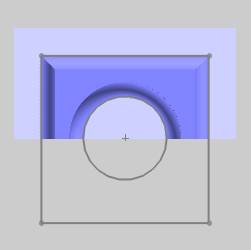
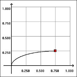
Convex Arc
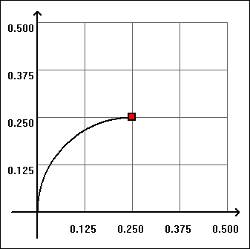

This cross-section type creates a raised arc
in the model using the following parameters.
- Radius - sets the distance
from the center of the arc to the edge of the arc.
- Start Angle - sets where
the arc begins and is tangent to adjacent surfaces in the model.
- End Angle - sets where the arc stops and is tangent to adjacent surfaces in the model.
Note: If theStart Angleis greater than theEnd Anglethe resulting surface is concave and the radius does not appear in the model. The angles should be within a sweep of 90 degrees, that is, neither value should exceed 90.
Concave Arc
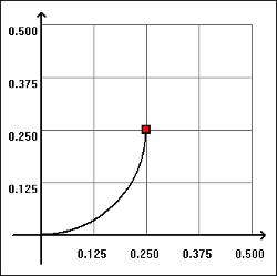
This cross-section type creates a sunken or depressed arc in the model using the following parameters.
- Radius - sets the distance
from the center of the arc to the edge of the arc.
- Start Angle - sets where
the arc begins and is tangent to adjacent surfaces in the model.
- End Angle - sets where the arc stops and is tangent to adjacent surfaces in the model.
Line
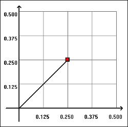

This cross-section type creates an angled wall on the model using the following parameters.
- Height - sets
the distance from the bottom of the Slope Angle to the top of the
Slope Angle. If looking at the results of this operation as a right
triangle, the height indicates the length of a leg and not the length
of the hypotenuse.
- Slope Angle - sets the angle of the resulting surfaces, relative to the stock of the model.
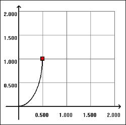
Convex Ellipse

This cross-section type creates a raised radial surface on the model using the following parameters.
- Major Axis -
sets the horizontal length of the ellipse.
- Minor Axis - sets the height of the surface created by the operation.
Concave Ellipse
This cross-section type creates a sunken or depressed radial surface in the model using the following parameters.
- Major Axis - sets the horizontal
length of the ellipse.
- Minor Axis - sets the height of the surface created by the operation.
Spline
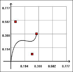
This cross-section type creates a contour using three control points as follows.
- Point 1(X-Y) - sets the
distance from the base geometry to the first control point in X/Y.
- Point 1(Z) - sets the distance
from the stock to the first control point of the contour in Z.
- Point 2(X-Y) - sets the
distance from the base geometry to the second control point of the
contour in X/Y.
- Point 2(Z) - sets the distance
from the stock to the second control point of the contour in Z.
- Point 3(X-Y) - sets the
distance from the base geometry to the third control point of
the contour in X/Y.
- Point 3(Z) - sets the distance from the stock to the third control point of the contour in Z.
Custom Cross Section
In addition to the six predefined cross-section shapes, you can select custom cross-section geometry. The custom cross section must be an open shape and it must be drawn (flat) in the XY plane. The cross section can be drawn anywhere in the graphics area, as long as it is drawn in the XY plane. The open shape can include lines, arcs, and splines.
Because embossed models cannot have undercut areas, any part of a custom cross section that would result in an undercut area results in a vertical wall. What this means is that although there are some limitations on the shape of the custom cross section, you can draw any open shape, and the software automatically uses as much of the shape as possible. If you cannot create the desired result, you may need to redraw the cross section.
To assign a custom cross section:
- In the Cross Section group of the emboss feature dialog box, select Custom.
- In the
 BobART
tree, right-click
BobART
tree, right-click  Cross Section Geometry, and
click Re/Select.
Cross Section Geometry, and
click Re/Select.
- In the graphics area, select the cross section geometry, and confirm the selection.
- Regenerate the model.
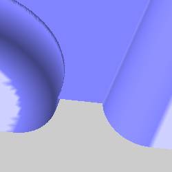
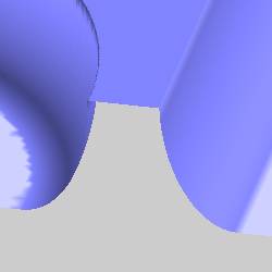
The following images show the result of using the same feature geometry and custom cross section for each of the three supported feature types.
Emboss Regular with Custom Cross Section

Emboss Swept with Custom Cross Section

Emboss Texture Weave with Custom Cross Section
