The Tool Adapter Definition
Introduction
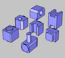
This topic explains how to create tool adapters for mounting lathe or mill (live) tools to the turret of a mill turn machine (lathe with live tooling). The Tool Adapter Definition dialog displays when you click Add Adapter in the Adapter Library.
Overview
Define Parameters for the Adapter
-
Name the adapter.
-
Define the Size:
- Use the system to create a basic block (cube)
-or-
- Assign your own custom geometry (.stl file)
-
Assign the (adapter) Mounting Location or the reference point used to mount the adapter to a turret station.
Note: When assigning custom geometry, the .stl file for the adapter should be placed in (and selected from) the following location: C:\BobCAD-CAM Data\**Current Version**\Technology\Adapters. Be sure to place the adapter (.stl file) in the appropriate folder, inch or metric, based on the unit type in which it was created.
Define Parameters for the Tool Mounting Points on the Adapter
-
Select the Tool Mounting Point (TMP) to enable its parameters.
- Change the name if desired.
-
Define the Mounting Location for the Tool Mounting Point to the adapter.
- Define the Tool Axial Direction.
- Define the Tool Radial Direction.
-
If there is more than one tool mounting point on the adapter, add a Tool Mounting Point and repeat previous steps.
Using the Preview Window
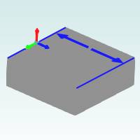
The Tool Adapter Definition dialog box contains a preview window to show the adapter and various coordinate systems: the adapter origin, adapter mounting location, and all tool mounting points on the adapter.
View Controls
The adapter preview uses the standard mouse controls for altering the viewing position of the preview.
- You can Rotate the view by dragging with the left mouse button in the preview window. (You can also drag with the middle mouse button.)
-
You can Pan the view by holding down Ctrl (on the keyboard) and dragging with the middle mouse button.
-
You can Zoom in or out using the scroll wheel (rolling the middle mouse button forward or backward).
Shortcut Menu Controls
You can right-click anywhere inside the preview window to open a shortcut menu with two view options: Fit All and Transparent.
Gnomon Size
The gnomon size slider can be adjusted to
increase or decrease the size of the gnomons (![]() ) that
indicate the various coordinate systems used to define the adapter.
) that
indicate the various coordinate systems used to define the adapter.
Define the Adapter
Adapter Description
Type a descriptive name for the adapter that makes it easy to identify.
Adapter Geometry
There are two methods that you can use to define the geometry for any adapter. You can use the system to create a basic cube or you can create and assign an .stl file that is used for the adapter geometry. It is highly recommended that you assign custom geometry using an .stl file, as the more accurate the adapter geometry the more accurate the machine simulation.
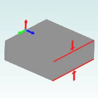
Size
The Size group contains the length, width, and height values that are used to create a basic cube for the adapter geometry. When you assign custom geometry using the Load STL button, these parameters become unavailable.
Tip: The
Size parameters for the adapter are in reference to the coordinate system
gnomon (![]() ) that displays tin the preview window. The
red arrow of the gnomon is the positive X direction, green is the positive
Y direction, and blue is the positive Z direction. The Size values are
automatically set when you load a custom (.stl) geometry file for the
adapter.
) that displays tin the preview window. The
red arrow of the gnomon is the positive X direction, green is the positive
Y direction, and blue is the positive Z direction. The Size values are
automatically set when you load a custom (.stl) geometry file for the
adapter.
Length
This is the distance of the adapter along the X-axis.
Width
This is the distance of the adapter along the Y-axis.
Height
This is the distance of the adapter along the Z-axis.
Loading Custom Adapter Geometry
View Preparing Custom Adapter Geometry
STL File Unit
Before assigning custom adapter geometry, select the proper unit type in which the original .stl file was created: Inch or Metric. This is important as it allows the software to create the adapter in the proper size.
Load STL
The Load STL button displays the Open dialog box for you to locate and select an .stl file to use as custom adapter geometry. The Size parameters become unavailable as they are automatically set based on the extents of the selected file.
Note: When assigning custom geometry, the .stl file for the adapter should be placed in (and selected from) the following location: C:\BobCAD-CAM Data\**Current Version**\Technology\Adapters. Be sure to place the adapter (.stl file) in the appropriate folder, inch or metric, based on the unit type in which it was created.
Adapter Mounting Location
The adapter mounting location defines the reference point that is used when mounting the adapter to a turret. (These parameters display at the top of the dialog box. This should not to be confused with the mounting location parameters for the tool mounting points.)
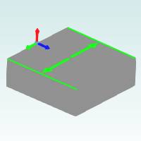
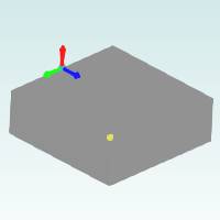
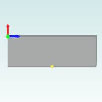
Mounting Location
The mounting location
XYZ values are used to shift the mounting location of the adapter in reference
to the adapter origin. The adapter origin is shown by the gnomon (![]() ) in the preview window. The mounting location is indicated
by a yellow sphere. Note that by default, the adapter origin and adapter
mounting location are the same.
) in the preview window. The mounting location is indicated
by a yellow sphere. Note that by default, the adapter origin and adapter
mounting location are the same.
-
X - sets the incremental distance from the adapter origin to the adapter mounting location along the X-axis.
-
Y - sets the incremental distance from the adapter origin to the adapter mounting location along the Y-axis.
-
Z - sets the incremental distance from the adapter origin to the adapter mounting location along the Z-axis.
Define the Tool Mounting Points
All parameters in the lower half of the Tool Adapter Definition dialog box are used to define the tool mounting points on the adapter. Any adapter may have one or more tool mounting points. Each tool mounting point contains a coordinate system to define the origin and axes directions that are used when mounting tools to the adapter. The following information explains how to define and add tool mounting points on the adapter.
Tool Mounting Points
The first part of defining a tool mounting point is to select one in the Tool Mounting Points list. By default there is only one tool mounting point, labeled TMP-1. You can add or remove tool mounting points using the Add or Delete buttons that display below the list.
-
Under Tool Mounting Points, click TMP-1 to select the first tool mounting point.
This enables all parameters in the dialog box for the selected mounting point. -
Define all parameters for the tool mounting point (the parameter descriptions follow these steps).
You can rename the mounting point to a more descriptive name to make it easier to identify later. -
If the adapter has more than one tool mounting point, click Add to create another tool mounting point.
-
Click the new mounting point in the list to enable all of its parameters and repeat the process.
Name
You can change the name of the tool mounting point from the default convention as needed. This name is used in the tool crib when mounting tools to the adapter.
Mounting Location
The mounting location
XYZ values are used to shift the tool mounting point of the adapter in
reference to the adapter origin. The adapter origin is shown by the gnomon
(![]() ) in the preview window. The tool mounting point
is indicated by another gnomon.
) in the preview window. The tool mounting point
is indicated by another gnomon.
-
X - sets the incremental distance from the adapter origin to the tool mounting point along the X-axis.
-
Y - sets the incremental distance from the adapter origin to the tool mounting point along the Y-axis.
-
Z - sets the incremental distance from the adapter origin to the tool mounting point along the Z-axis.
Tool Axial Direction
This parameter is used to define the axes directions of the tool mounting point coordinate system. In other words, you define what machine axis direction (positive or negative) aligns with the axial direction of the tool when mounted to the adapter.
Tool Radial Direction
This parameter is used to define the axes directions of the tool mounting point coordinate system. In other words, you define what machine axis direction (positive or negative) aligns with the radial direction of the tool when mounted to the adapter.