The CAM Flyouts
Introduction
This topic will explain the CAM Flyouts, explain where they can be accessed from, and explains the options found in them.
The CAM Flyouts
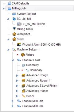
The CAM Flyouts are designed to do two things. First, they provide a way to quickly view information you may be looking for easily. Secondly, they provide a way to edit some values without the need to open a dialog and search for them in that dialog. The CAM Flyouts can be toggled by selecting/deselecting the Enable CAM Tree Flyouts check box in the settings dialog. When the toggle is on, as they are in the lower left image, certain items in the CAM Tree will be shown with >> to the right of them. These are the items that offer a flyout. Simply hover over the >> to view the flyout. Then click elsewhere to close the flyout. Turning the Flyouts off will remove them from the CAM Tree, as shown in the image on the lower right. 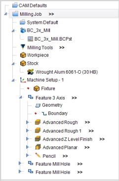
Navigation
The CAM Flyouts appear in the CAM Tree next to the following items:
- Job
- Tools
- Stock
- Machine Setup
- Feature
- Operation
CAM Flyout Parameters
The following section will describe the options found in each of the flyouts. When looking at the data presented to you, you will notice some of the text seems to be grayed out. These are values that cannot be edited from the flyout dialog.
Job
At the job level, hovering over the flyouts will give you access to Program Data, and Toolpath Data. This will also allow you to edit the program number. Once the program number is changed, clicking Apply will finalize the change.
| ^ | Program Data | ||
| Program Number |
|
||
| Number of Tools |
|
||
| Number of Operations |
|
||
| ^ | Toolpath Data | ||
| Only Posted Operations |
|
||
| Feed Distance |
|
||
| Rapid Distance |
|
||
| Total Distance |
|
||
| Feed Time |
|
||
| Rapid Time |
|
||
| Total Time |
|
||
|
|||
- Only Posted Operations - will determine whether operations set not to post will be calculated in the Toolpath Data.
 - Operations that are set not to post out, will not be included in the Toolpath Data values.
  - Operations that are set not to post out, will be included in the Toolpath Data values.
Tools
Hovering over the Tools flyout will display the data for the tools used in the job. The data seen in this flyout will be the same data displayed in the Assigned Tools dialog. None of these values can be edited, but the following is an example of the tool information on a Mill job.
| Tool Number | Tool Diameter | Corner Radius | Tool Type | Tool Label |
| 1 | 0.5000 | ENDMILL ROUGH | 1/2 FLAT ROUGH ENDMILL | |
| 2 | 0.2500 | ENDMILL FINISH | 1/4 FLAT FINISH ENDMILL |
Stock
Hovering over the Stock flyout will display the bounding area of the stock. This bounding area is based on the position and orientation of each of the machine setups in relation to the stock. This information cannot be edited.
|
||||||
|
||||||
|
|
Total | Minimum | Maximum | |||
| Length-X |
|
|
|
|||
| Length-Y |
|
|
|
|||
| Length-Z |
|
|
|
|||
- Machine Setup - will allow you to select which of the machine setups the stock information is based on.
Machine Setup
Hovering over the Machine Setup flyout will display the Setup Origin, which cannot be edited. The Clearance value, and the Work Offset values it displays can be edited.
| ^ | Setup Origin | ||
| X |
|
||
| Y |
|
||
| Z |
|
||
| ^ | Clearance | ||
| Clearance |
|
||
| ^ | Work Offset | ||
| Work Offset # |
|
||
| X |
|
||
| Y |
|
||
| Z |
|
||
|
|||
- Only Posted Operations - will determine whether operations set not to post will be calculated in the Toolpath Data. - Operations that are set not to post out, will not be included in the Toolpath Data values. - Operations that are set not to post out, will be included in the Toolpath Data values.
Note: While, in general, the above image represents the flyout of the Machine Setup, the available parameters vary between jobs.
Feature
Hovering over the Feature flyouts will give you access to Feature Data, and Toolpath Data. While the Feature Data can be edited, the Toolpath Data cannot.
| ^ | Feature Data | ||
| Rapid Plane |
|
||
| Feed Plane |
|
||
| Top of Feature |
|
||
| Depth |
|
||
| Only Posted Operations |
|
||
| ^ | Toolpath Data | ||
| Cutting Distance |
|
||
| Rapid Distance |
|
||
| Feed Time |
|
||
| Rapid Time |
|
||
| Total Time |
|
||
|
|||
- Only Posted Operations - will determine whether operations set not to post will be calculated in the Toolpath Data. - Operations that are set not to post out, will not be included in the Toolpath Data values. - Operations that are set not to post out, will be included in the Toolpath Data values.
Note: While, in general, the above image represents the flyout of the Features, the available parameters vary depending on whether the feature is a Mill, Turning, or Wire EDM feature.
Operation
Hovering over the Operation flyouts will give you access to Tool Data, Feeds and Speeds data, and Toolpath Data. While the Feature Data can be edited, the Toolpath Data cannot.
| ^ | Tool Data | ||
| Tool Number |
|
||
| Tool Label |
|
||
| Tool Diameter |
|
||
| ^ | Feeds and Speeds | ||
| Use System Feeds and Speeds |
|
||
| SFM |
|
||
| Feed per Tooth |
|
||
| Plunge Feed per Tooth |
|
||
| Spindle RPM |
|
||
| Cutting Feedrate |
|
||
| Plunge Feedrate |
|
||
| ^ | Toolpath Data | ||
| Cutting Distance |
|
||
| Rapid Distance |
|
||
| Feed Time |
|
||
| Rapid Time |
|
||
| Total Time |
|
||
|
|||
- Use System Feeds and Speeds - will determine whether the Feeds and Speeds can be edited. - The system Feeds and Speeds are used. - Feeds and Speeds can be manually edited.
Note: While, in general, the above image represents the flyout of the Operations, the available parameters vary depending on what type of Operation.