Groove Feature Parameters
Introduction
Whether a groove is placed on a part for the fitting of another part, or for an O-ring, and whether the groove is square, round or angular, a groove is an indention on the part. As such, the Groove feature will allow you to create an indention of any size or shape needed on the part. The Lathe Grooving feature offers two operations, each of which has many variables that can be tailored to your needs.
Material Approach
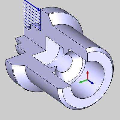
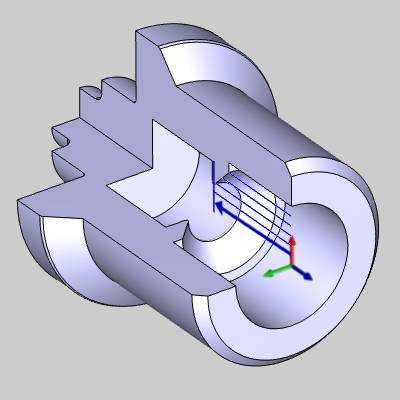
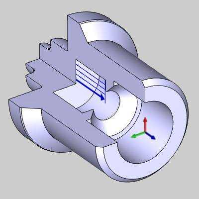
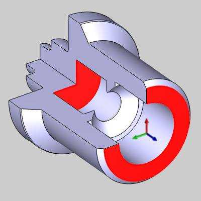
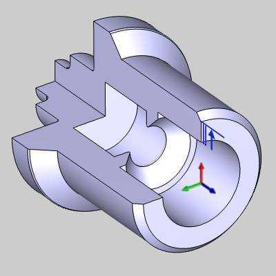
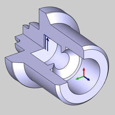
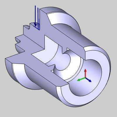
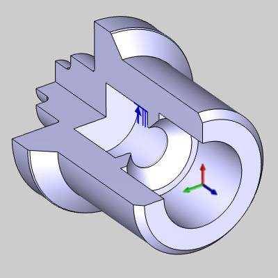
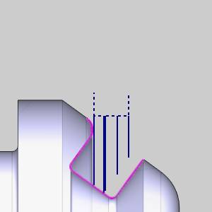
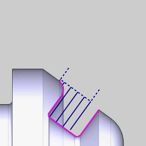
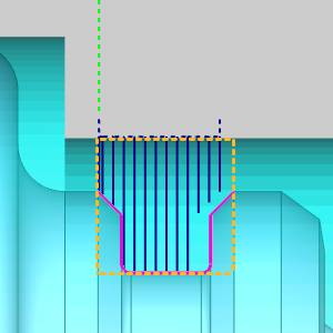
Rapid Plane - is the height at which the tool can rapid safely within a single operation. This value visualized as a dotted line in the toolpath and is an incremental distance above the Top of Feature defined in the Constraints section.
|
Rapid Crashing |
Rapid Lifted |
|
|
|
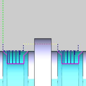
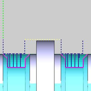
Warning: Rapids that are going through portions of the part are not highlighted in the software but merely go straight through. This rapid has been highlighted for visual aid in this help system.
Feature Parameters
Feature Type
- OD -
Sets the feature to the outer diameter of the part.
- ID -
Sets the feature to the inner diameter of the part.
- Face -
Sets the feature to faces normal to Z+.
- Back Face - Sets the feature to faces normal to Z-.
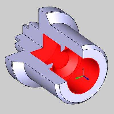
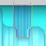
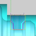
Region - Sets the features default settings for the type of toolpath being used. This will set the default rapids, entry and exits as well as default tool selection and direction of cut.
- 1
- See examples.
- 2 - See examples.
|
OD |
OD Region 1 |
OD Region 2 |
|
|
|
|
|
|
|
|
|
ID |
ID Region 1 |
ID Region 2 |
|
|
|
|
|
|
|
|
|
Face |
Face Region 1 |
Face Region 2 |
|
|
|
|
|
|
|
|
|
Back Face |
Back Face Region 1 |
Back Face Region 2 |
|
|
|
|
Note: Region selections are not only for particular sections of the part. Even though, for a given situation, a particular region choice will set the feature up to be better suited for the task, the user may adjust the remaining parameters to match their particular needs.
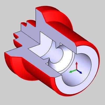
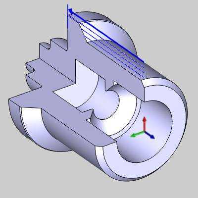
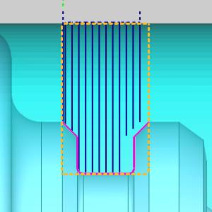
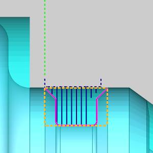
Rotate - Selecting this check box will give you the ability to rotate the feature so the toolpath is aligned with the geometry. This can be done with:
|
Lathe Feature |
Rotated Lathe Feature |
|
|
|
- Angle - Type in the angle the feature is to be rotated.
- Pick -
Select pick to hide the Lathe Wizard and launch Pick Angle dialog in the
 Pick Wall
- allows you to click an entity
to set the toolpath parallel to. Clicking the entity once will
add the geometry to the Selected Geometry list. Click OK to confirm.
Pick Wall
- allows you to click an entity
to set the toolpath parallel to. Clicking the entity once will
add the geometry to the Selected Geometry list. Click OK to confirm.
 (Delete) - removes
the highlighted item from the list.
(Delete) - removes
the highlighted item from the list.The list box will list the entity currently selected for the function.  Pick Floor
- allows you to click an entity
to set the toolpath perpendicular to. Clicking the entity once will
add the geometry to the Selected Geometry list. Click OK to confirm.
Pick Floor
- allows you to click an entity
to set the toolpath perpendicular to. Clicking the entity once will
add the geometry to the Selected Geometry list. Click OK to confirm.
(Delete) - removes
the highlighted item from the list.The list box will list the entity currently selected for the function.
Constraints
The constraints define the area in which the toolpath will be generated.
Top of Feature - Defines the height at which the rapid plane will be incremental from.
-
From
Stock - Sets the Top of Feature to the highest point of the
stock diameter.
-
From Geometry - Sets the Top of Feature to the highest point of the selected
feature geometry.

-
Custom
- Set the Top of Feature from the highest point of the selected
feature geometry to the value entered.
-
Pick - allows you to select a point or the snap point of an entity to set the height of the feature.
Note: The Pick value is incremental from the highest point of the selected geometry for the feature. If geometry selection was skipped at this point, the Pick function will not return a value.
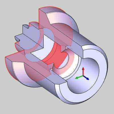
Extension
Extensions allow you to extend the feature geometry without the need to create additional CAD geometry. The extension will be added or subtracted along the chain of entities.
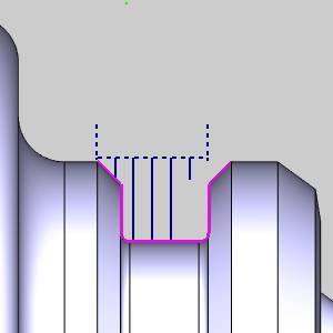
![]() - No extension will be added to the feature geometry.
- No extension will be added to the feature geometry.
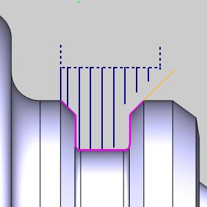
![]() - Will allow you to define an extension to the feature geometry.
- Will allow you to define an extension to the feature geometry.
|
Extension Off |
Extension Start On |
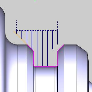
Extension End On |
|
|
|
|
Start - is the first of the selected chain of entities.
- Distance- sets the amount of extension added to the tangent direction
of the chain.
 Angle - While cleared the extension will added to the geometry to the tangent
direction.
Angle - While cleared the extension will added to the geometry to the tangent
direction. Angle- Select
this check box to set the extension at the angle entered.
Angle- Select
this check box to set the extension at the angle entered.- Relative to geometry - Select this check box to set the
angle of the extension relative to the tangency of the first entity. Relative to geometry -
While cleared the angle of the extension will be absolute.
End - is the last of the selected chain of entities.
- Distance - sets the amount of extension added to the tangent direction
of the chain.
- Angle - While cleared the extension will added to the geometry to the tangent
direction. Angle- Select
this check box to set the extension at the angle entered.
- Relative to geometry - Select this check box to set the
angle of the extension relative to the tangency of the last entity. Relative to geometry -
While cleared the angle of the extension will be absolute.
Next Topic
After defining the feature parameters, click Next> > to go to the Machining Strategy page.